Guided Co-Modulated GAN for 360º Field of View Extrapolation — Supplementary Materials
This document aims to provide additional results and analysis for our proposed method presented in the main paper. We start by showing some examples of our test set. It is worth mentioning that none of the images are seen during the training. Next, we provide additional results on the field of view extrapolation. Next, we show different editing results for various indoor and outdoor input images and target labels to show how well our suggested method works for editing with diverse conditions. Following that, we present an in-depth analysis of the success of editing for our approach based on the type of input images and target labels. Next, we provide extensive results to compare our editing method and InterfaceGAN. We provide a detailed explanation of virtual object insertion and spatially varying image-based lighting using our technique in section nine. Finally, we conclude this document by showing results of face editing using our method to demonstrate the broader impact of our approach.
Table of contents
- Image formation model
- Architecture detail (complements sec. 3.4)
- Evaluation dataset (complements sec. 4.1)
- Supplementary field of view extrapolation results (extends fig. 4)
- High-resolution result (complements sec. 4.2)
- Editing results (extends fig. 5)
- Linear interpolation in g space (extends sec. 6)
- Percentage of success of the guidance process (extends fig. 6)
- Editing with our method vs. InterfaceGAN (extends sec. 5.3)
- Virtual object compositing (extends sec. 6)
- Guided face editing
- Nearest neighbors
- Movie scenes
- References
1. Image formation model
As is commonly done in the literature[2], we frame $360º$ field of view extrapolation as out-painting in a latitude-longitude (or equirectangular) panoramic representation. We therefore warp the input image $\bo{x}$ to a equirectangular representation according to a simplified camera model, i.e.,
$\bo{p}_{im} = \bo{K}\bo{R}\bo{p}_{w}$
Here, $\bo{p}_{w}$ represents a 3D point in world coordinates (whose origin coincides with the center of projection of the camera, hence no translation), and $\bo{p}_{im}$ its projection (in homogeneous coordinates) on the image plane. We employ the pinhole camera model with common assumptions (principal point is the image center, negligible skew, unit pixel aspect ratio[17]), hence $\bo{K} = {diag}([f \; f \; 1])$, where $f$ is the focal length in pixels.
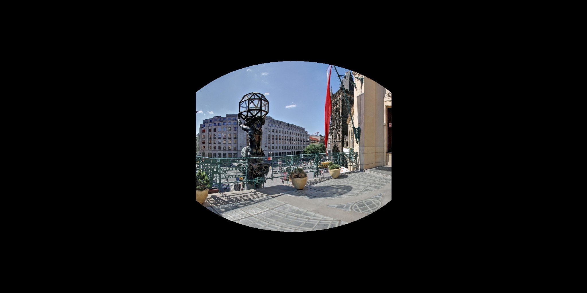
The rotation matrix $\bo{R}$ can be parameterized by roll $γ$, pitch $β$, and yaw $α$ angles. Since an arbitrary image possesses no natural reference frame to estimate $α$, we set $α=0$. We also take $γ=0$ as in [2], hence $\bo{R} = \bo{R}_x(β)$. The following figure illustrates our image formation model.
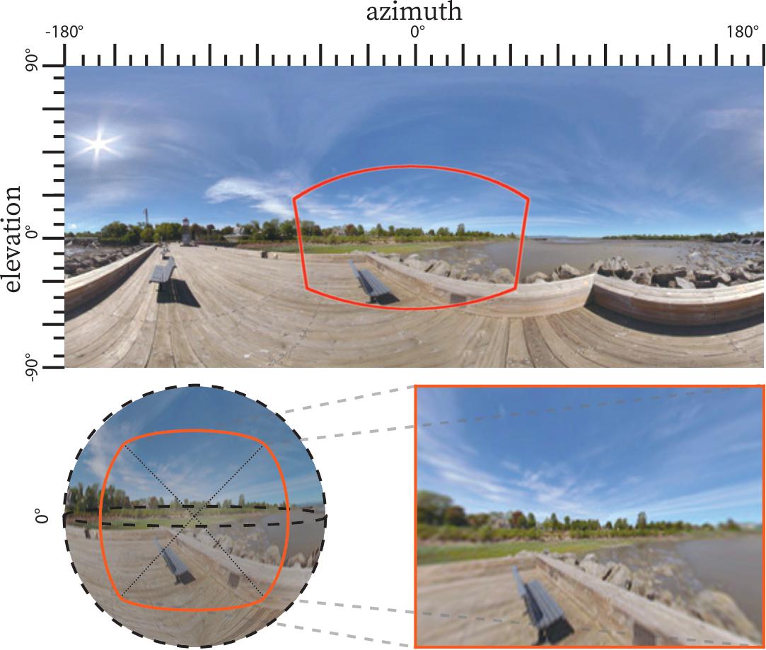
Figure 1.1: When a camera takes a picture (inset right), it samples a part of the environment around it, which can be represented in 2D as a latitude-longitude $360º$ panorama image (top).
2. Architecture detail
We build upon the StyleGAN2[15] architecture for the synthesis $S$ and mapper $M$ networks. We follow [16] for the encoder $E$, which is composed of a sequence of blocks that each halve the feature spatial dimensions. We use as many blocks as necessary to reach a $8 × 4$ resolution, the input size of our synthesis network. Each of those blocks is comprised of two convolutional layers ($3×3$ kernels) followed by a $2×$ downsampling. The feature tensor between these two layers is used as skip link injected in the synthesis network at the corresponding layer. A single convolutional layer with a $1×1$ kernel is added at the beginning of the encoder. All layers use the fused bias-and-activation operators proposed by [15]. For the training, we use the same loss function and follow the same training process as StyleGAN2[15].
To speed-up the training of the synthesis network, the ResNet-18 features were precomputed from the panorama dataset with $(h_α=90º, β=0º)$.
3. Evaluation dataset
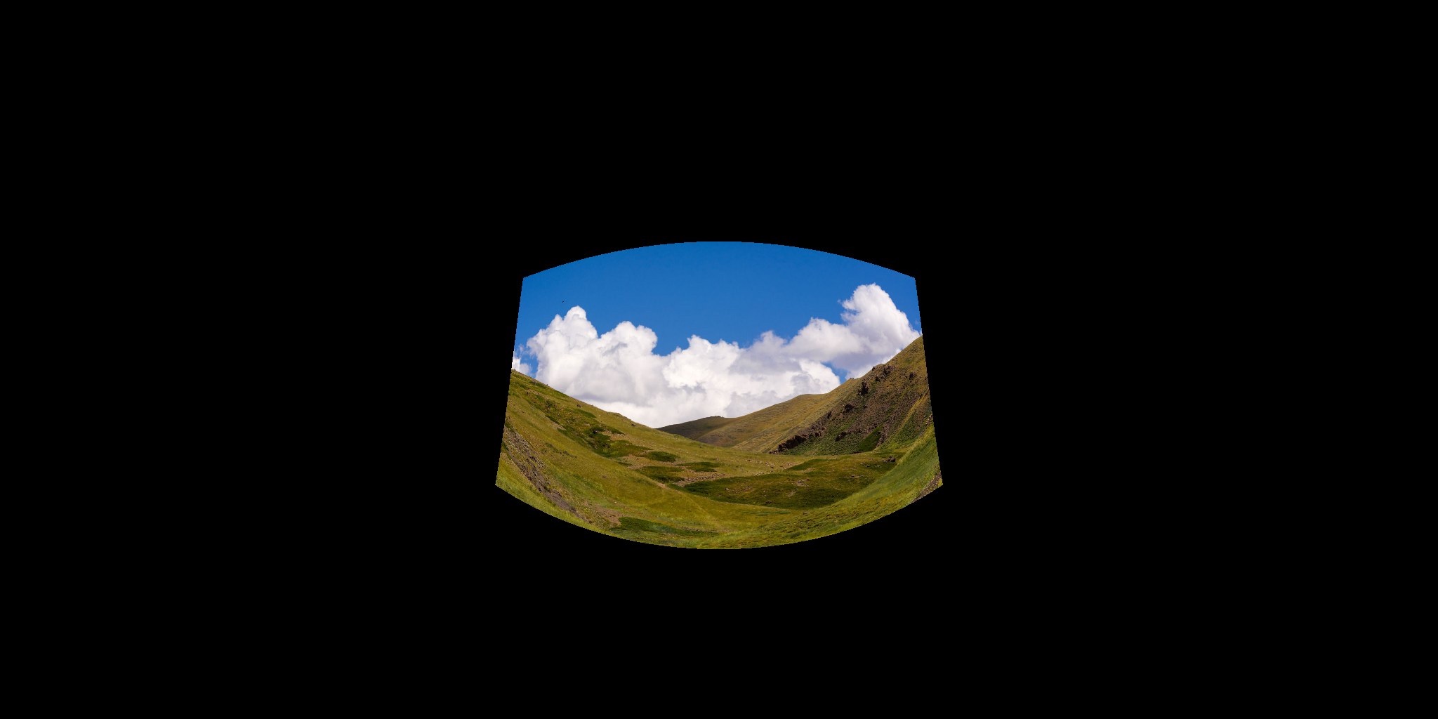
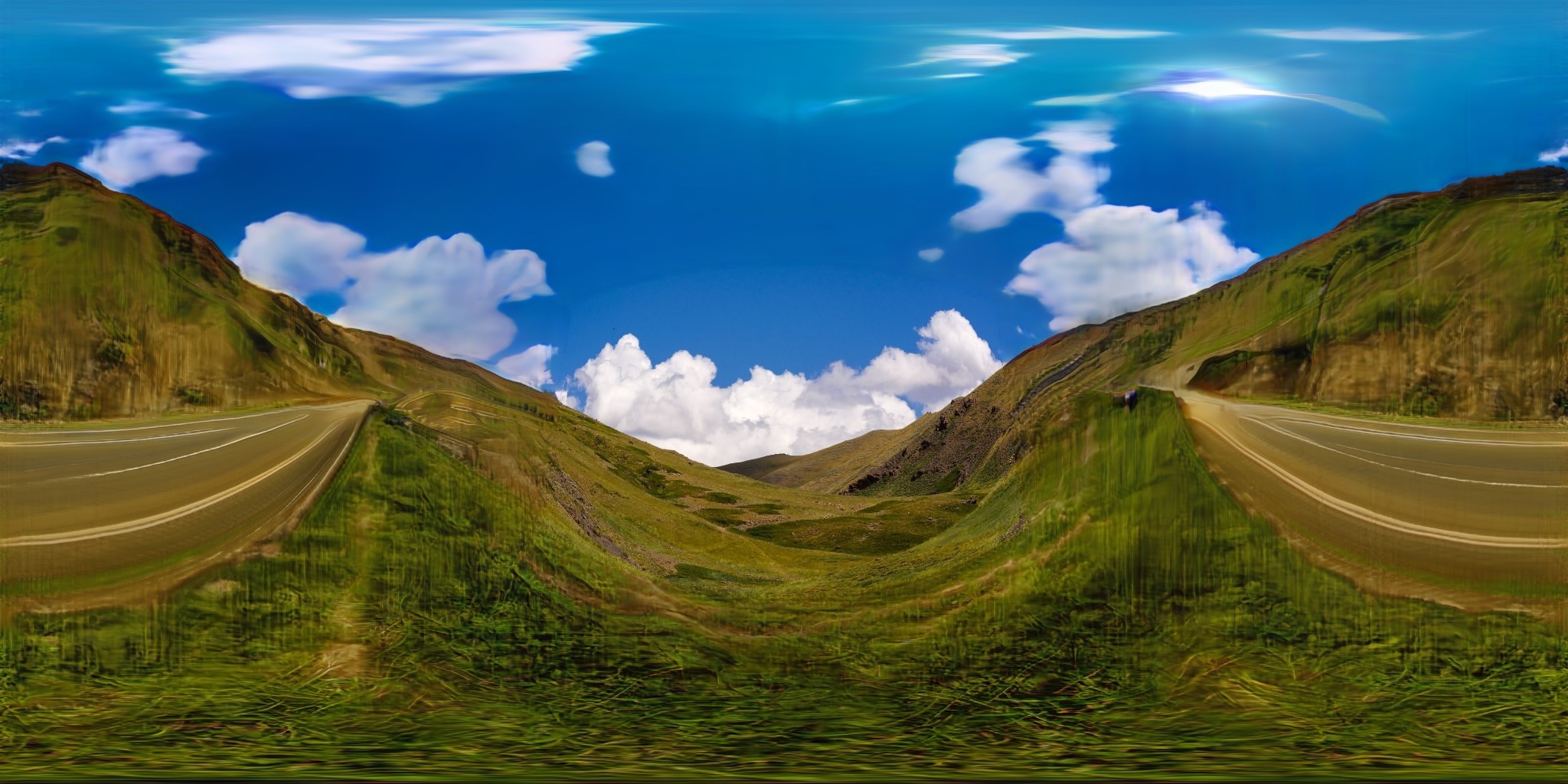
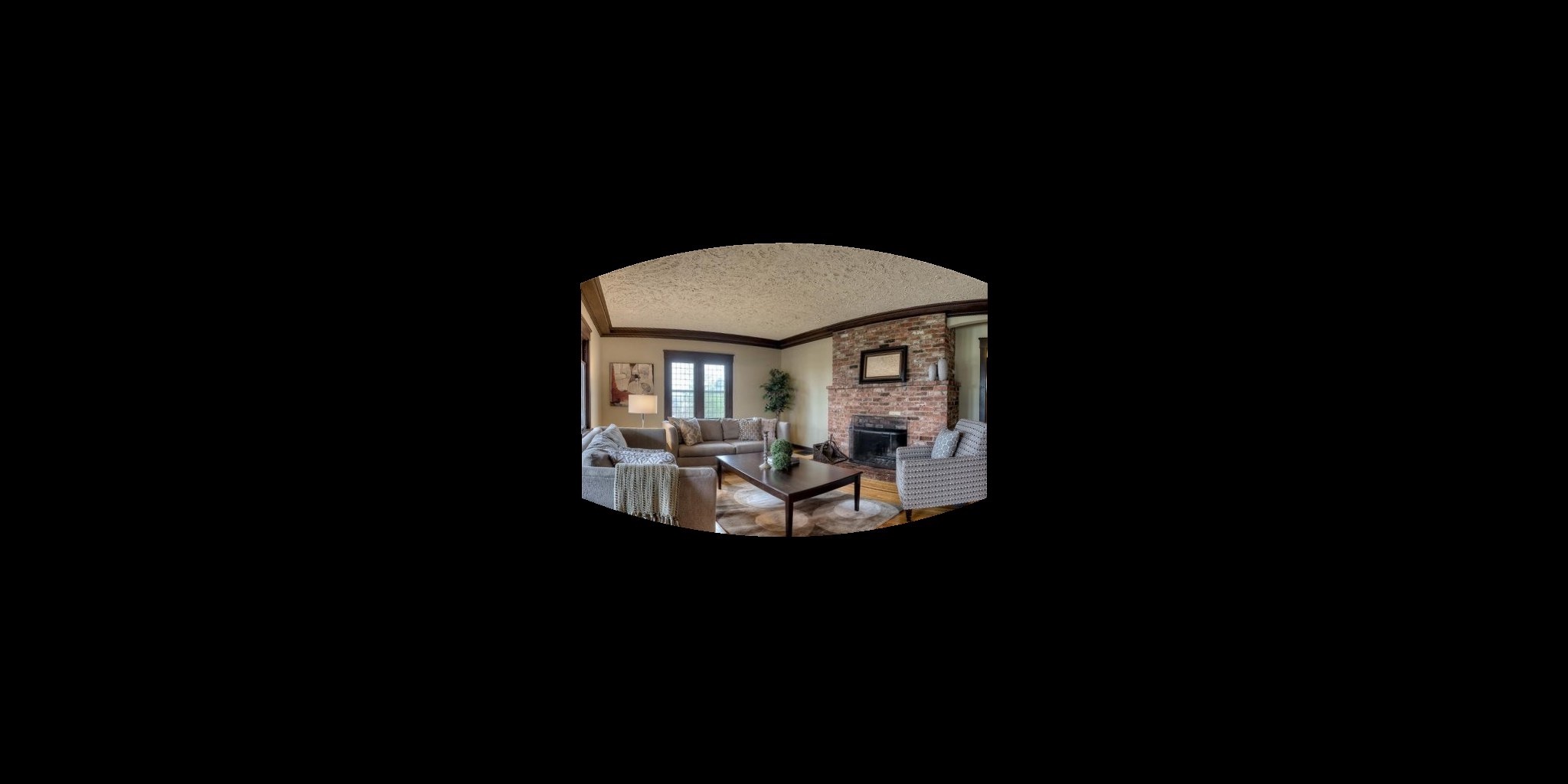
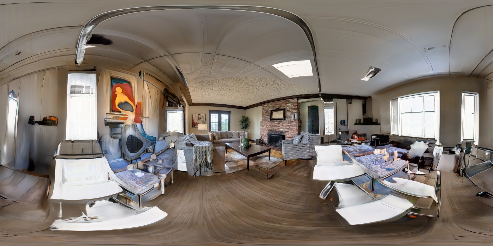
Here are some examples of the test set, presented in section 4.1 of the paper. This test set will be released publicly.
Image
Mask
Panoramic projection
GT
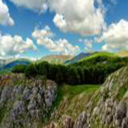

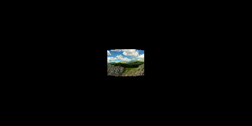
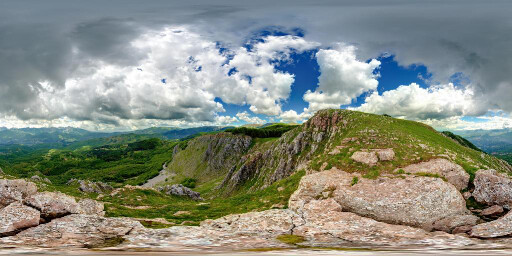


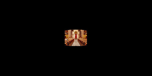
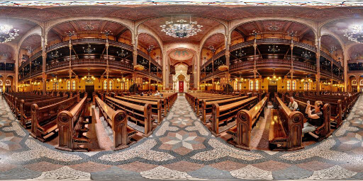
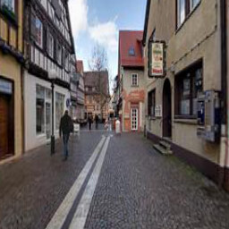
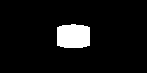
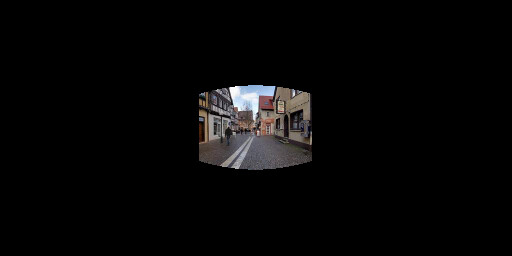
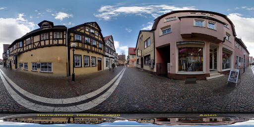
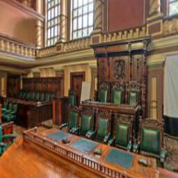
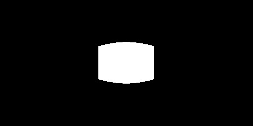
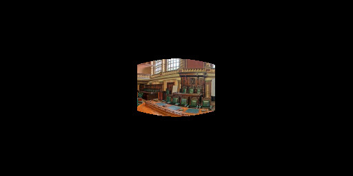
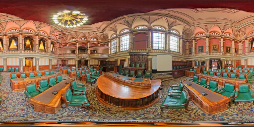
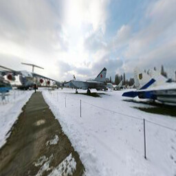

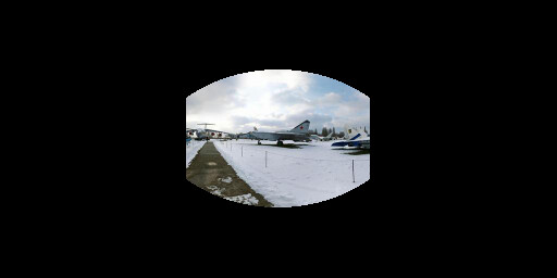
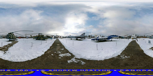
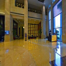

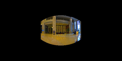
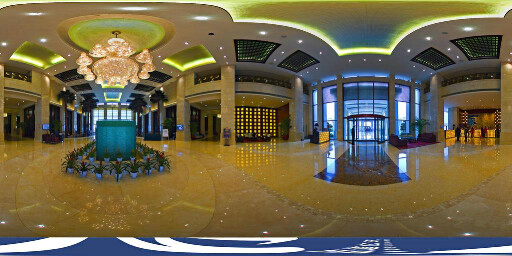
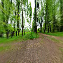

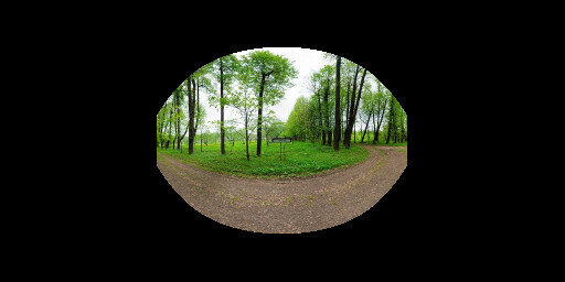
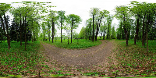
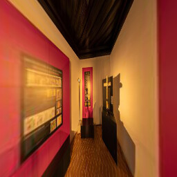

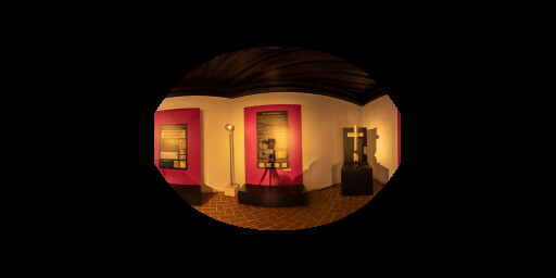
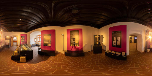
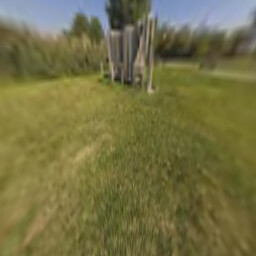
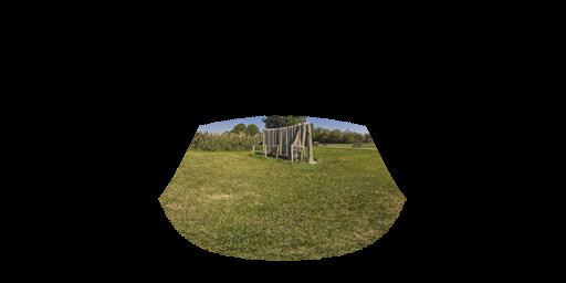
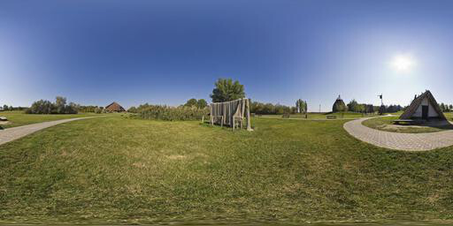
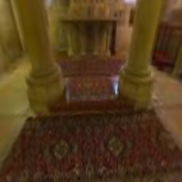

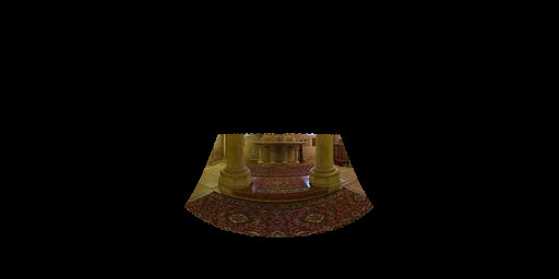
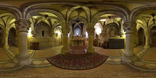
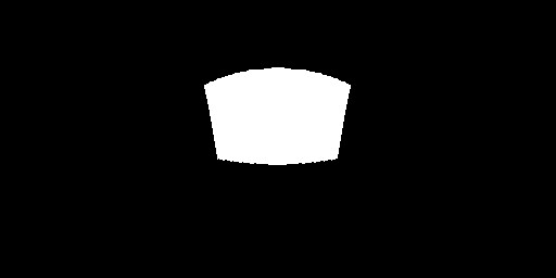
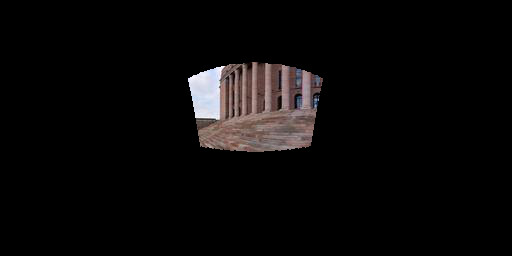
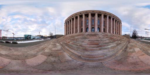
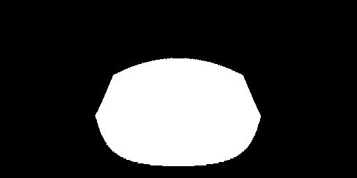
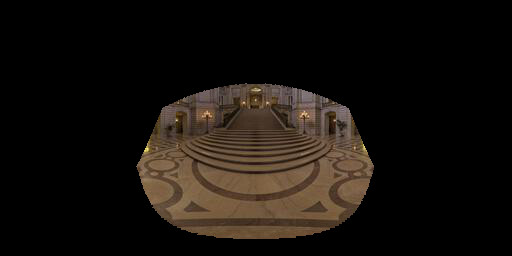
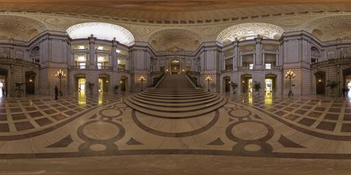
Figure 3.1: Examples of the test set used for qualitative and quantitative evaluations of our proposed method and state of the art.
4. Field of view extrapolation results
We present additional results for the task of field of view extrapolation as an extension to fig. 3. Each collider contains examples for different test sets. Please consult section 4.1 of the main paper for more information.
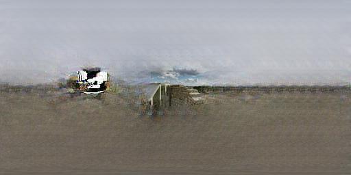
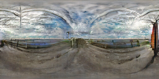
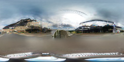
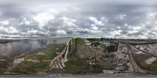
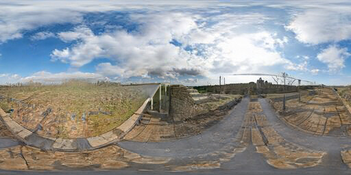
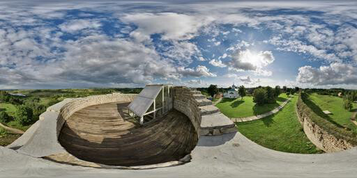
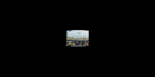
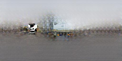
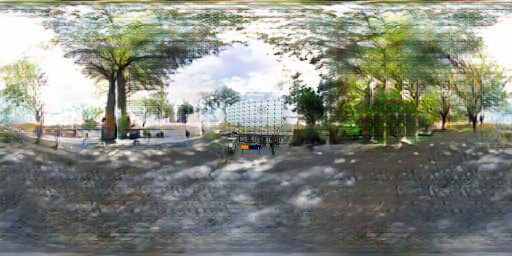
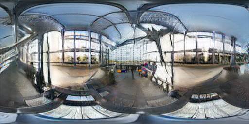
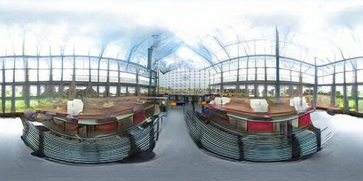
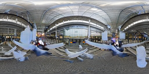
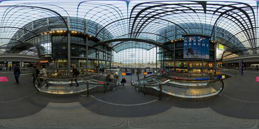
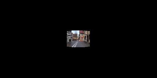
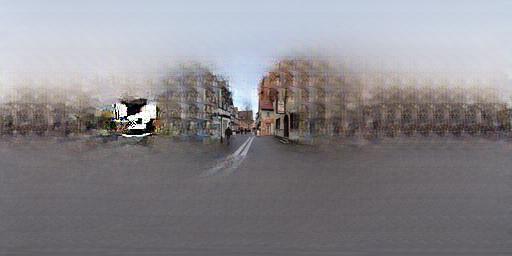
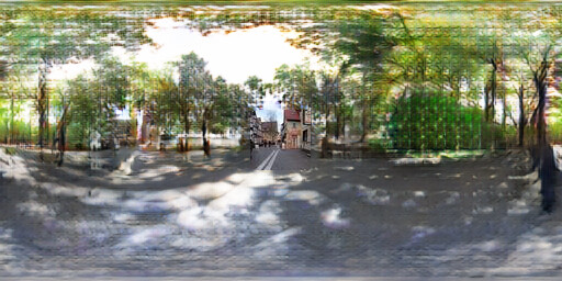

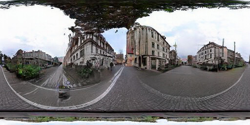
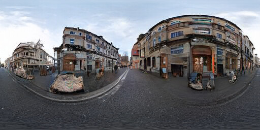
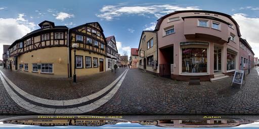
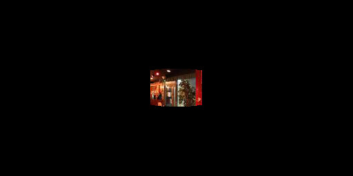
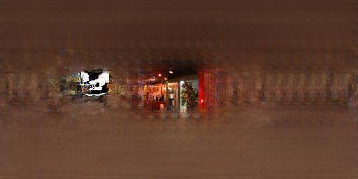
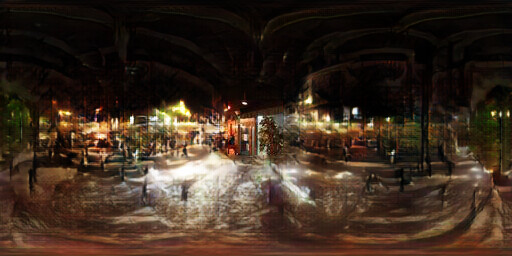
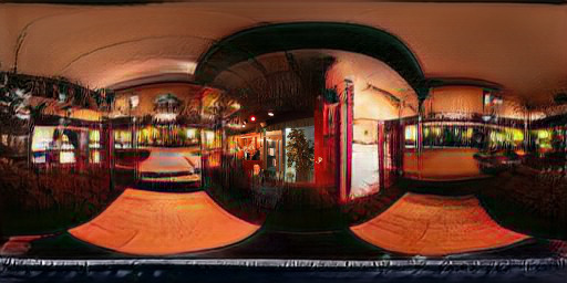
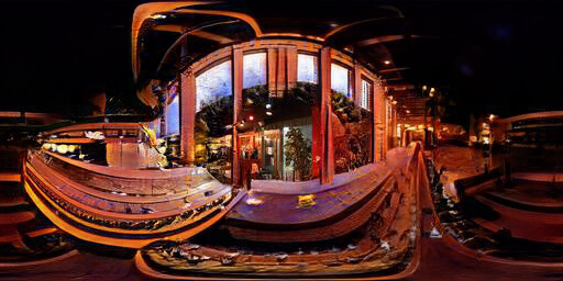
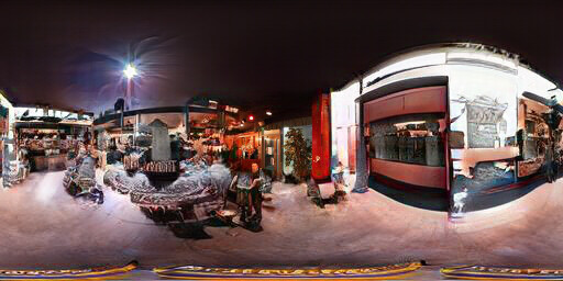
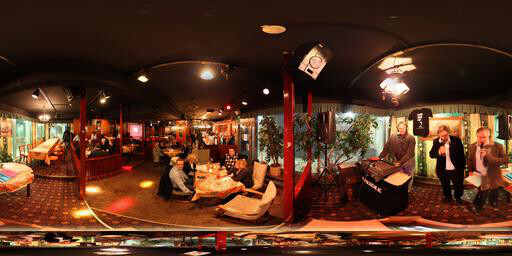
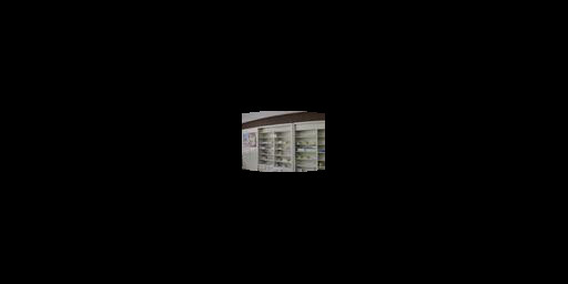
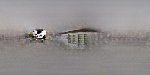
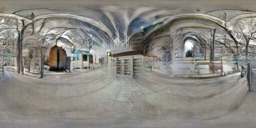
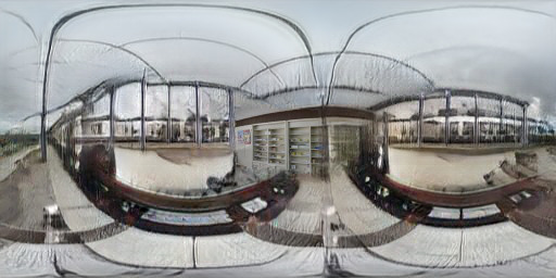
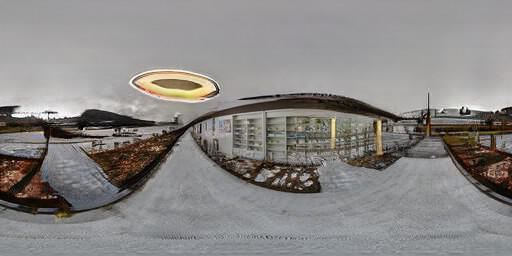
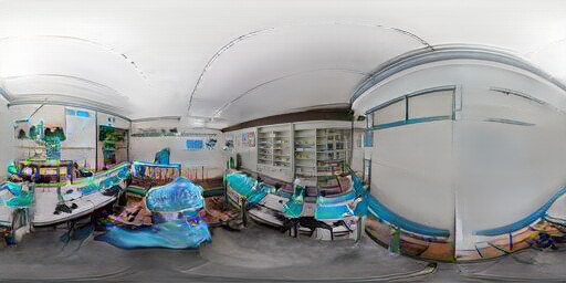
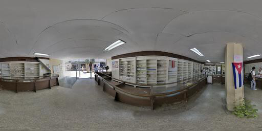
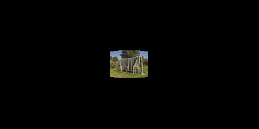
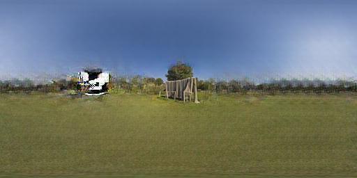
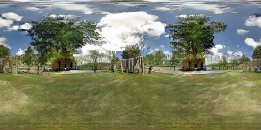

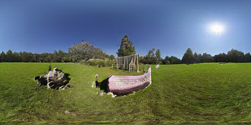
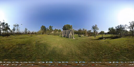
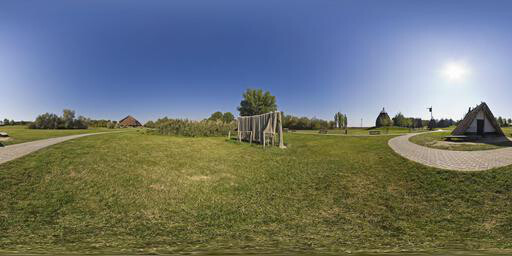
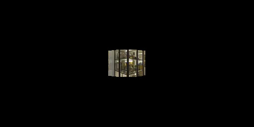
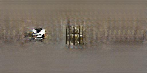
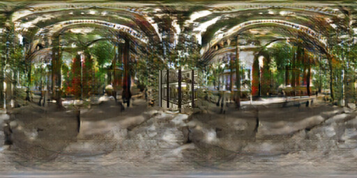
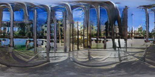
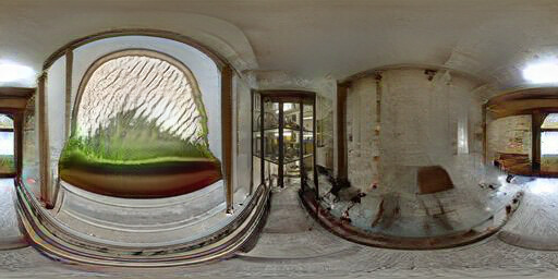
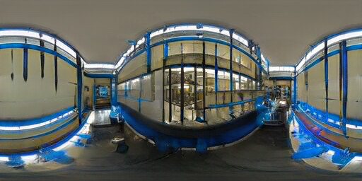
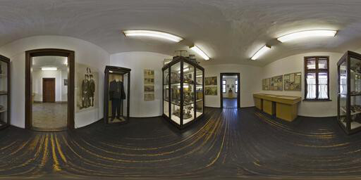
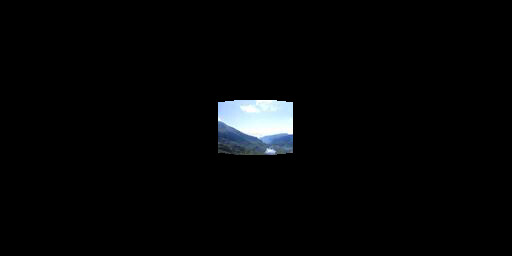
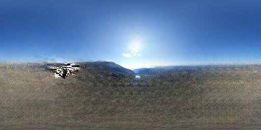
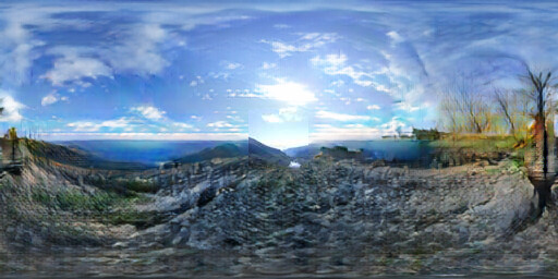
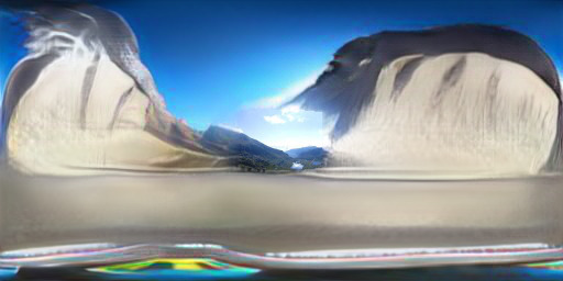
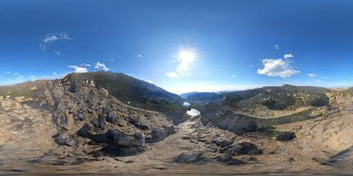
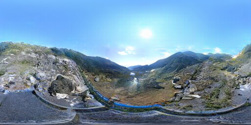
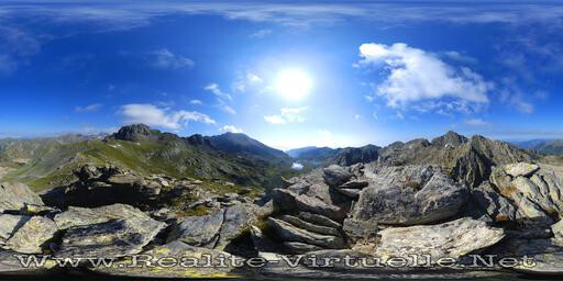
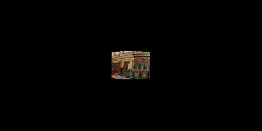
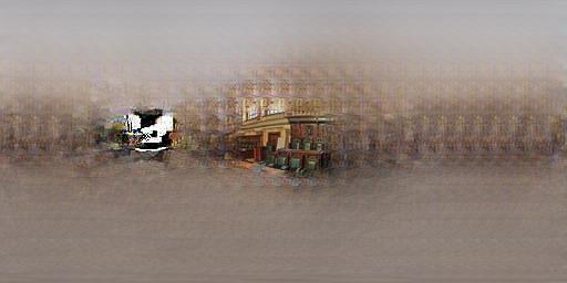
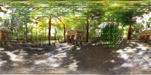

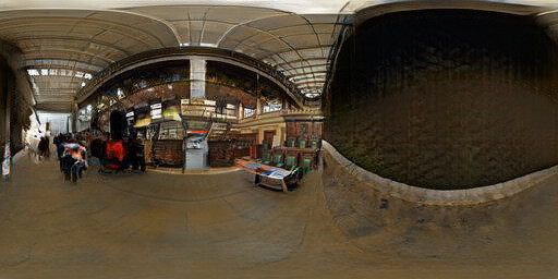
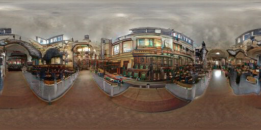
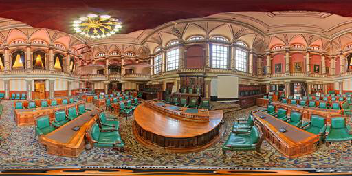
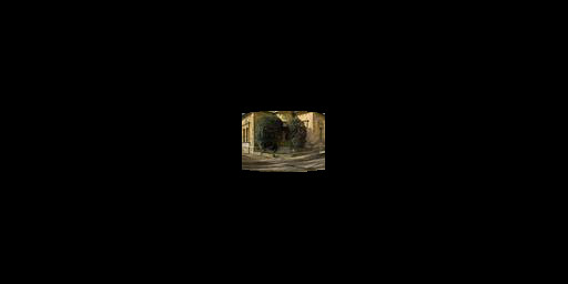
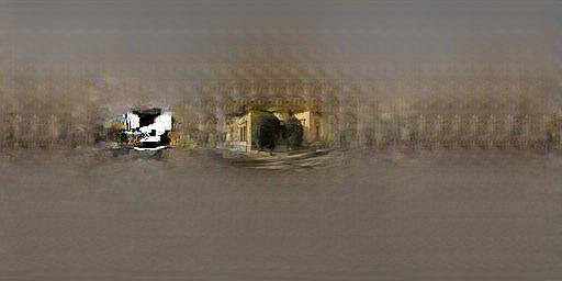
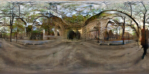
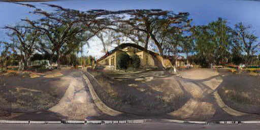
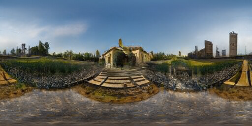
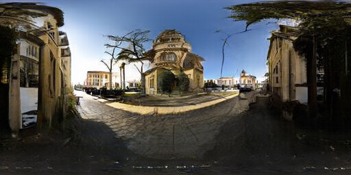
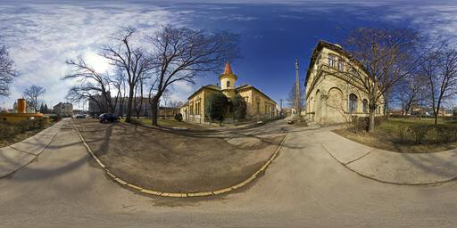
Figure 4.1: Extended results of field of view extrapolation for the test set of FOV 40˚


Figure 4.2: Extended results of field of view extrapolation for the test set of FOV 60˚


Figure 4.3: Extended results of field of view extrapolation for the test set of FOV 90˚


Figure 4.4: Extended results of field of view extrapolation for the test set of FOV 120˚
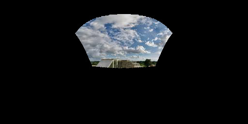
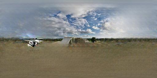

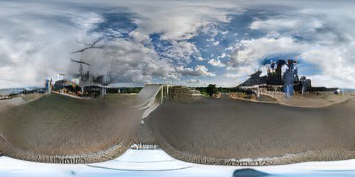
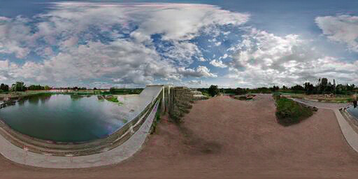
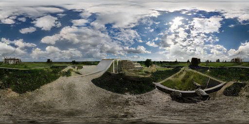

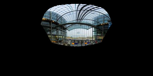
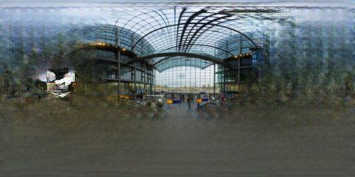

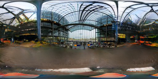
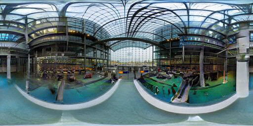
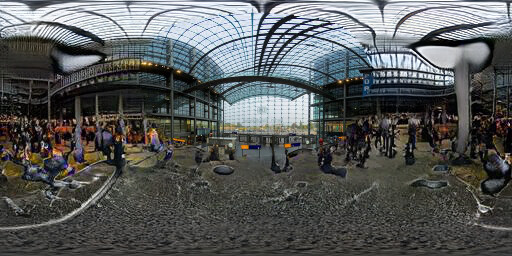

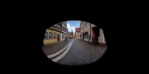
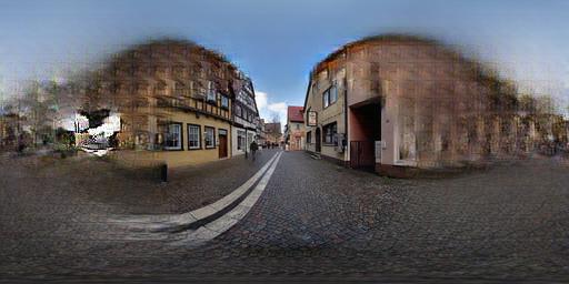

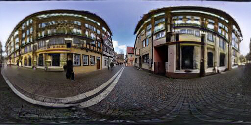
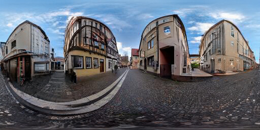
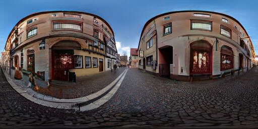

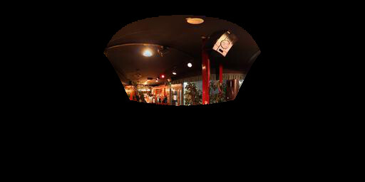
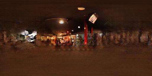

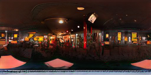
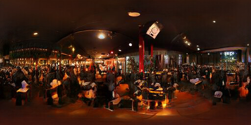
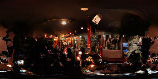

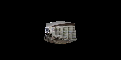
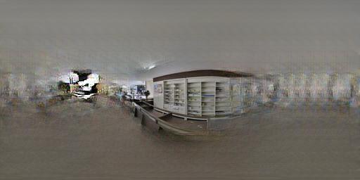

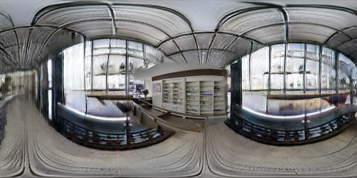
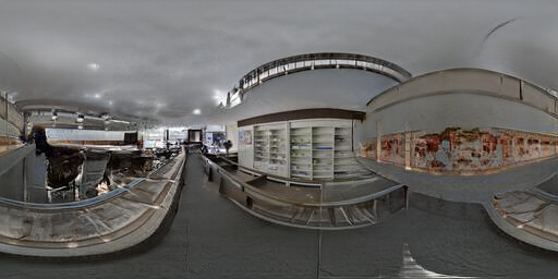
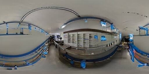

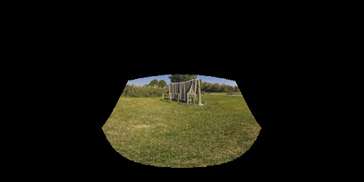
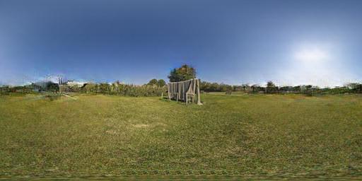

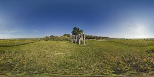
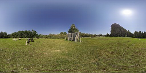
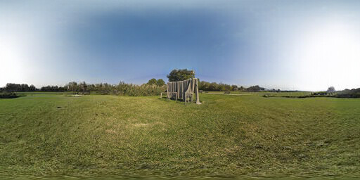

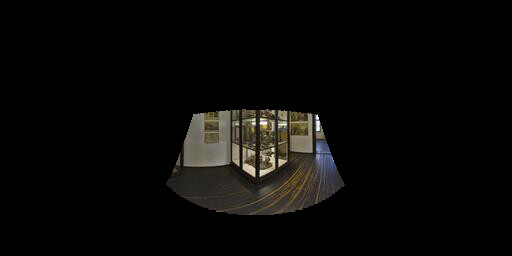
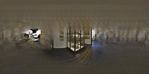

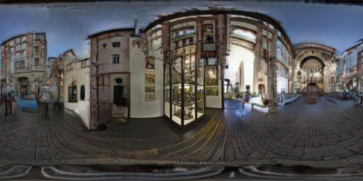
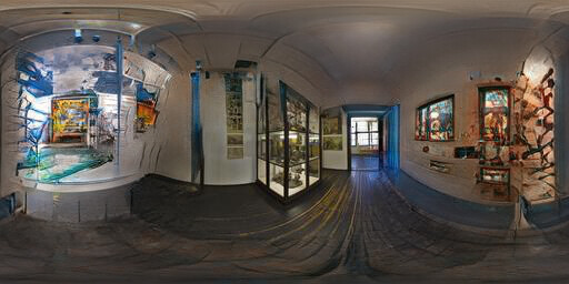
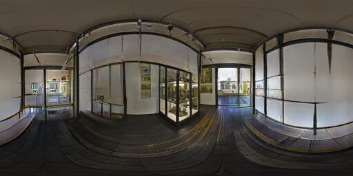

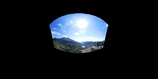
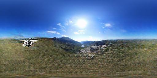

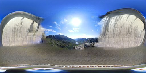
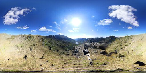
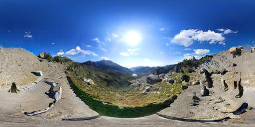

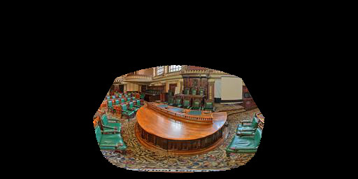
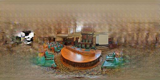

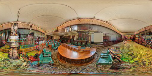
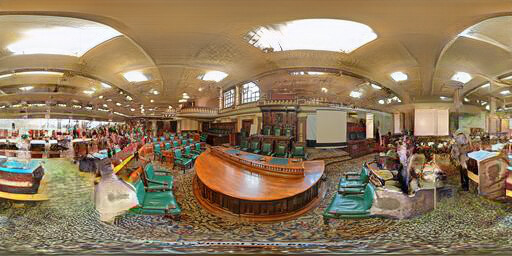
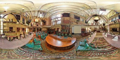

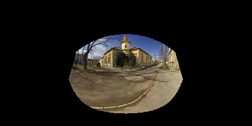
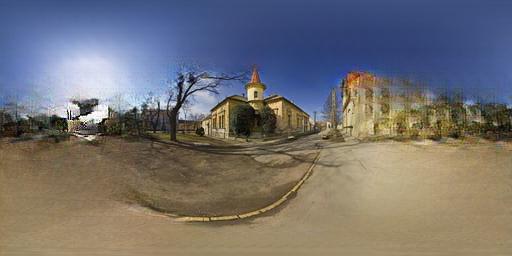

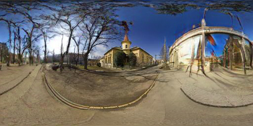
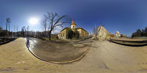
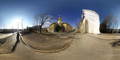

Figure 4.5: Extended results of field of view extrapolation for the "mixed" test set. Please consult the paper for more details.
5. High resolution results
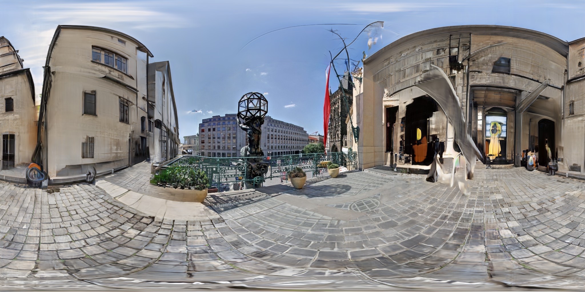
Our method can generate high-resolution, well-detailed panoramas. To show the generative power of our approach, we train it on 2K resolution panoramas. We present some of these high-resolution results in the following figure. Please click on each image to see them in full resolution.
Figure 5.1: High resolution panoramas generated using our method
6. Editing results
In order to show the performance of editing using our method and provide more results for editing, we choose ten outdoor scenes from the test set and ten labels from the top-1 labels of the train set. Then, we apply editing on all these images. Folowing you can find the results. We provide the success rate of each target label next to it to indicate how well the editing process works.
Input
Image Conditioned
to Tundra
Ground Truth
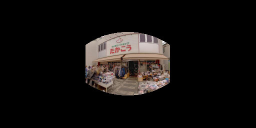
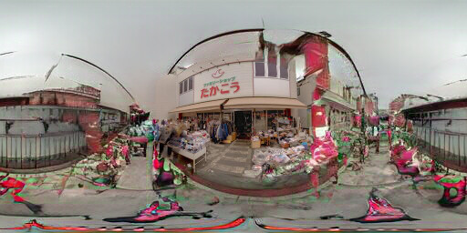
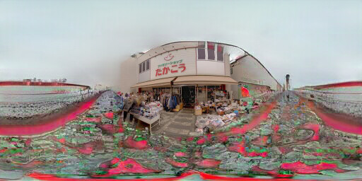
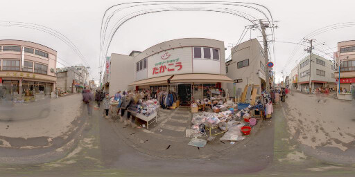
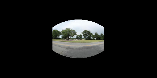
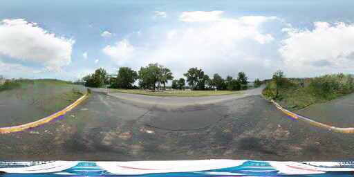
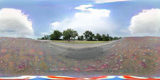
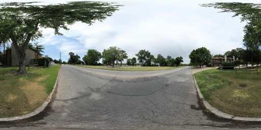
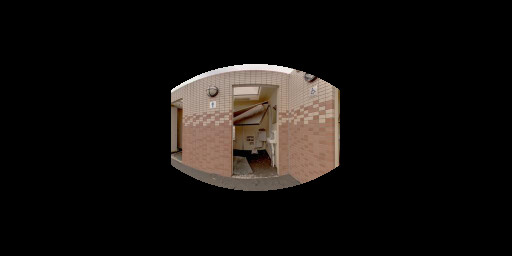
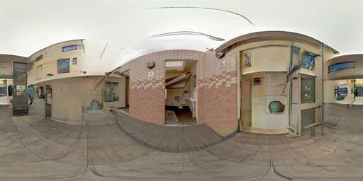
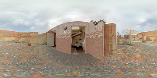
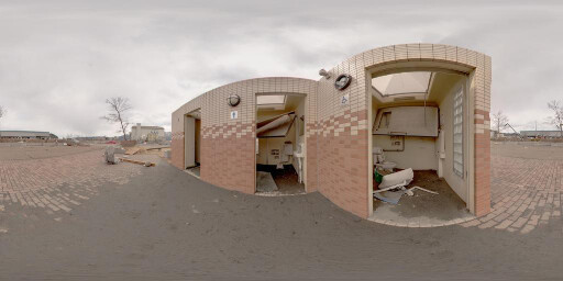
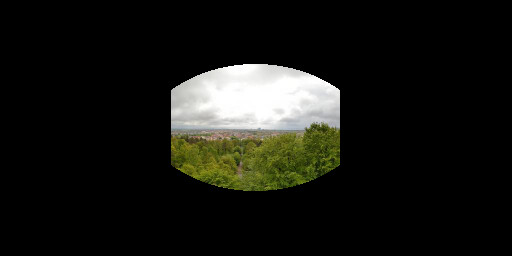
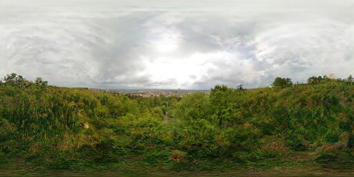
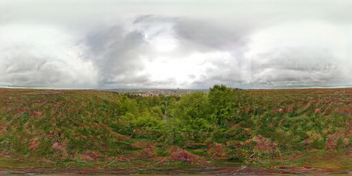
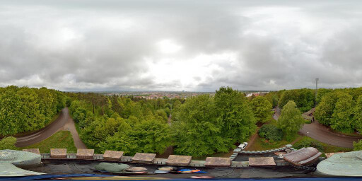
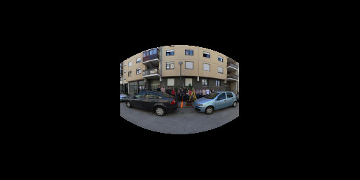
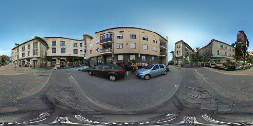
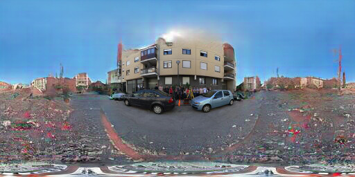
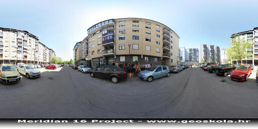
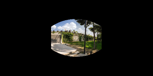
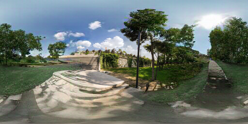
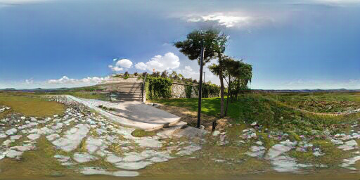
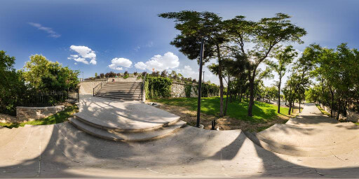
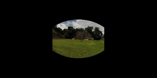
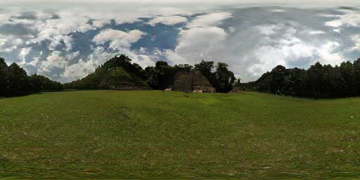
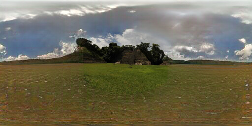
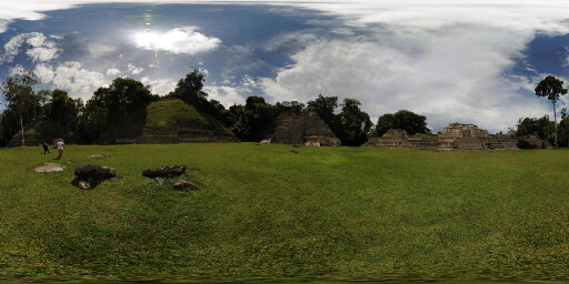
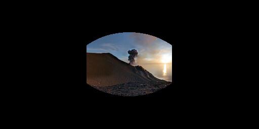
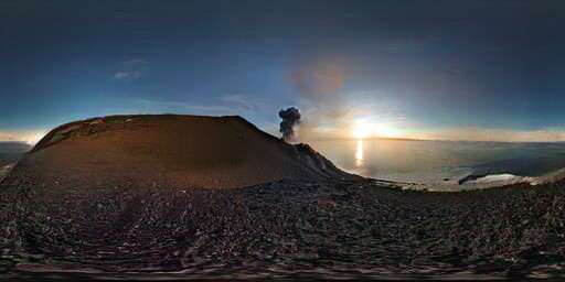
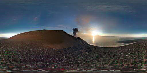
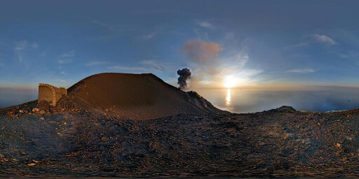
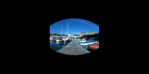
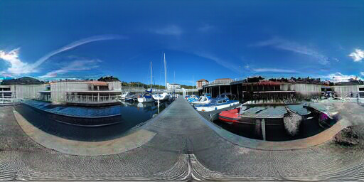
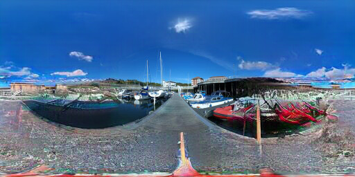
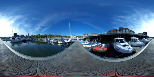
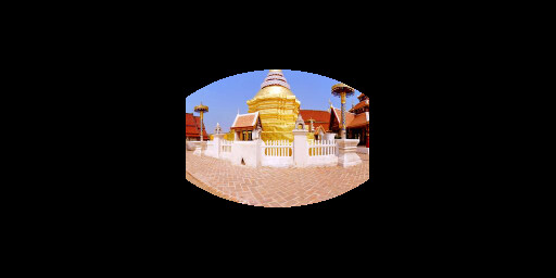
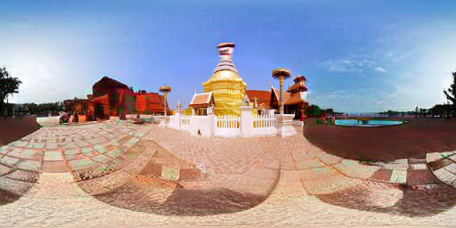
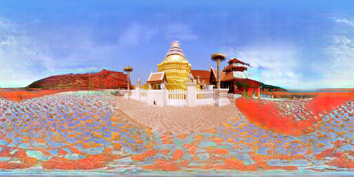
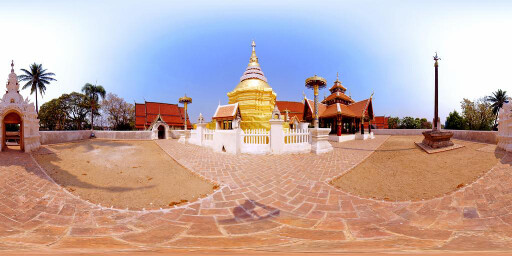
Figure 6.1: Extended results of optimizing the label "Tundra"
Input
Image conditioned
to Sky
Ground truth


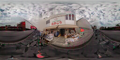


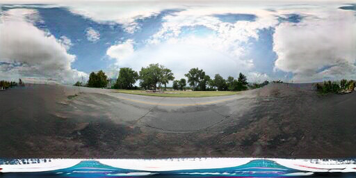


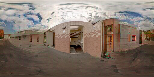


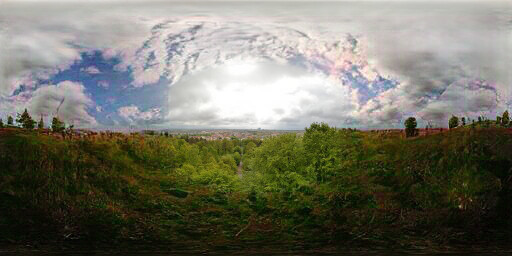


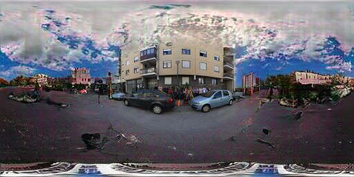


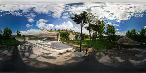


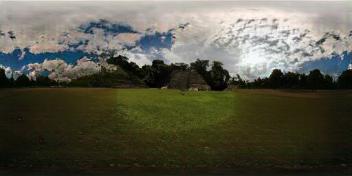


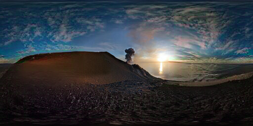


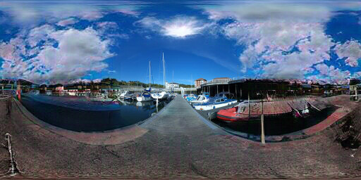


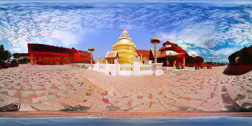

Figure 6.2: Extended results of optimizing the label "Sky"
Input
Image conditioned
to Snow field
Ground truth


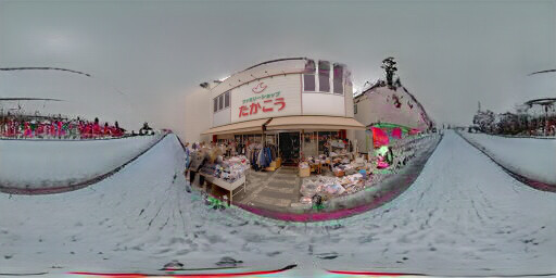


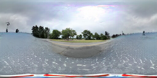


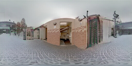


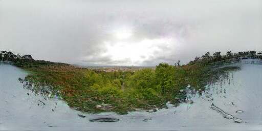


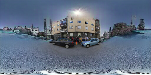


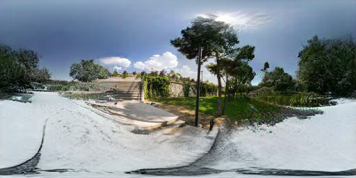


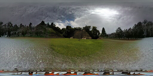


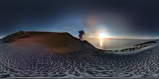


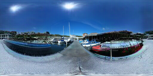


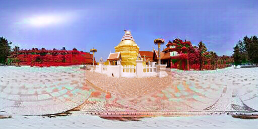

Figure 6.3: Extended results of optimizing the label "Snow Field"
Input
Image Conditioned
to Beach
Ground Truth


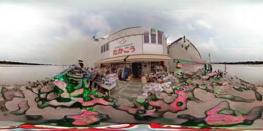


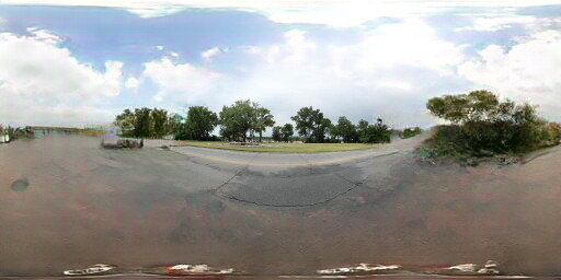


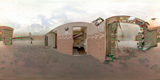


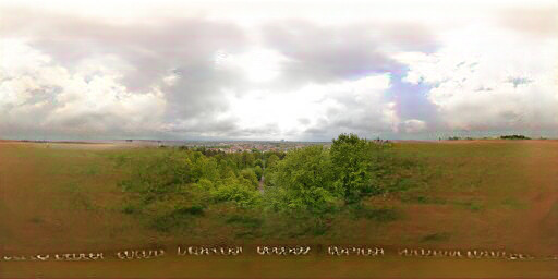


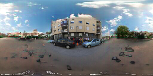


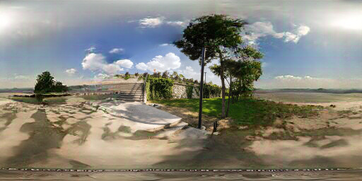


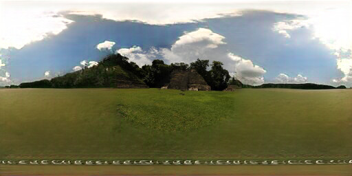


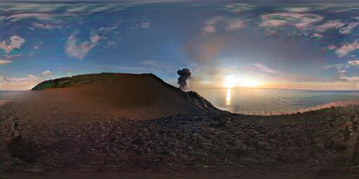


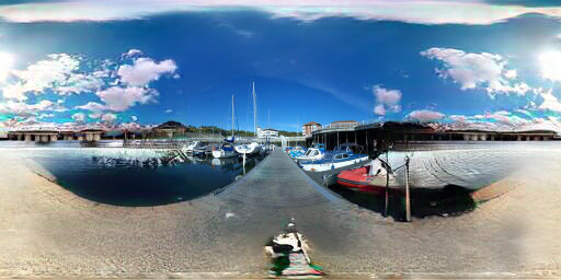


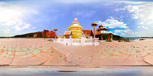

Figure 6.4: Extended results of optimizing the label "Beach"
Input
Image Conditioned
to Mountain Path
Ground Truth


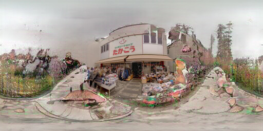


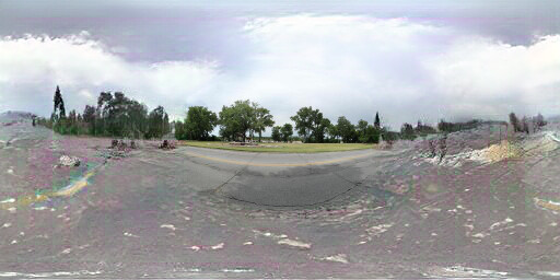


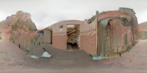


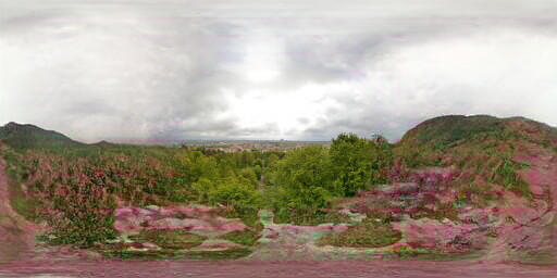


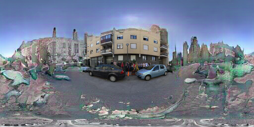


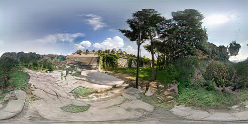


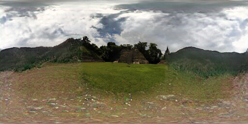


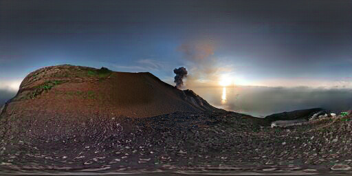


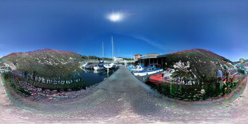


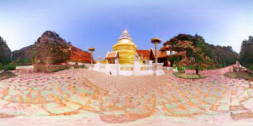

Figure 6.5: Extended results of optimizing the label "Mountain Path"
Input
Image Conditioned
to Cliff
Ground Truth


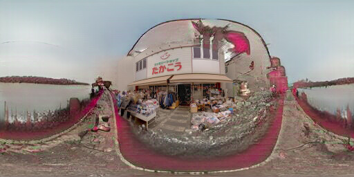


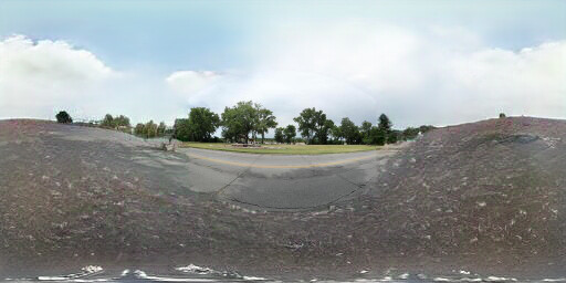


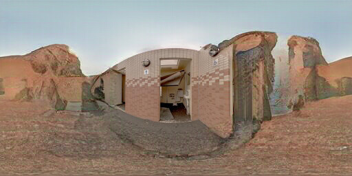


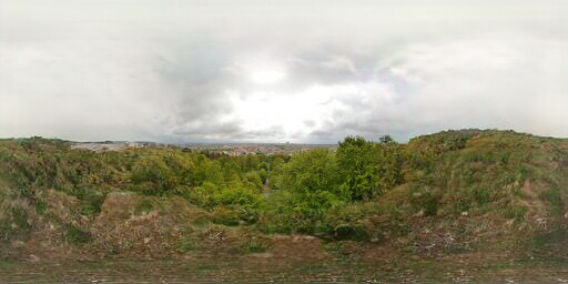


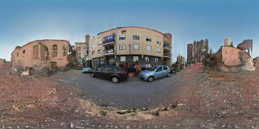


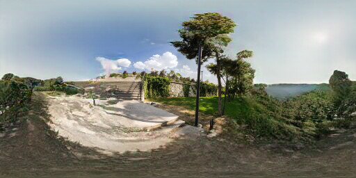


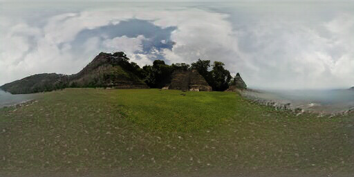


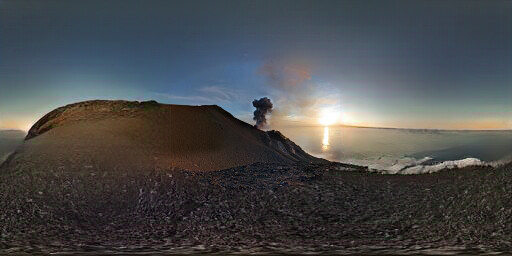


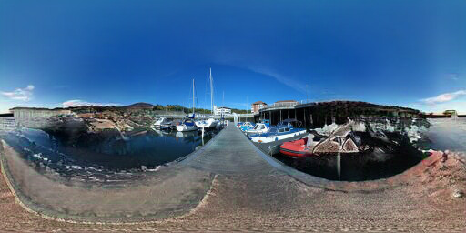


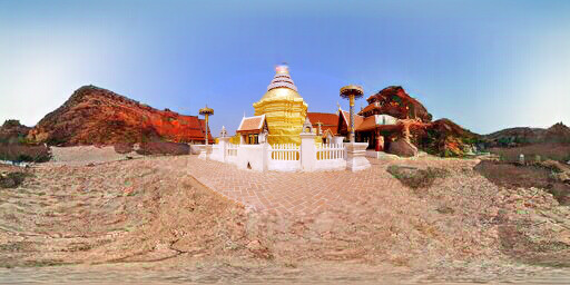

Figure 6.6: Extended results of optimizing the label "Cliff"
Input
Image Conditioned
to Picnic Area
Ground Truth


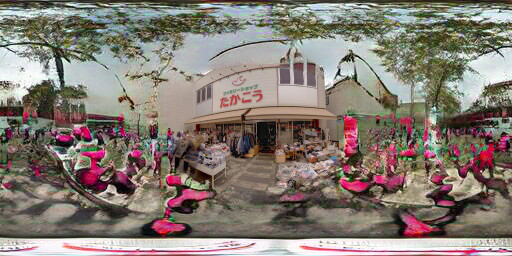


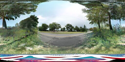


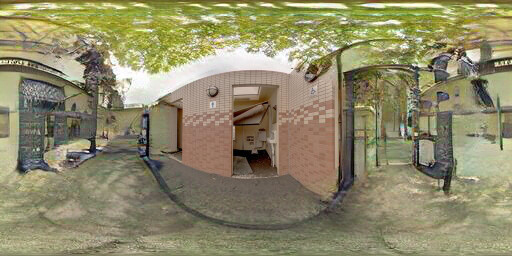


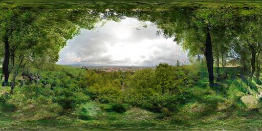


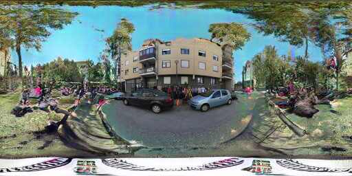


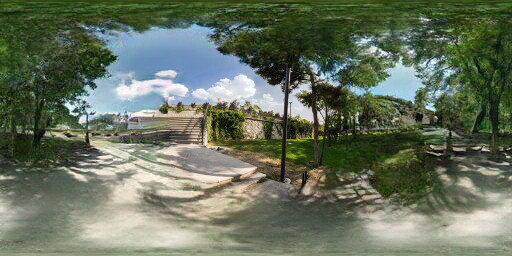


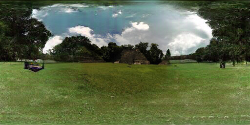


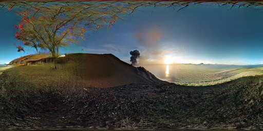


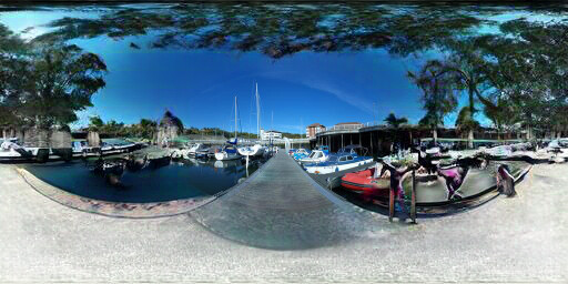


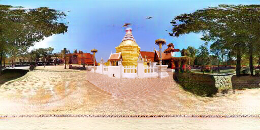

Figure 6.7: Extended results of optimizing the label "Picnic area"
Input
Image Conditioned
to Lawn
Ground Truth


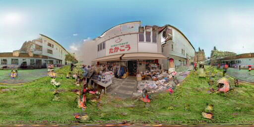


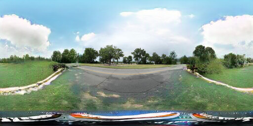


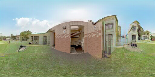


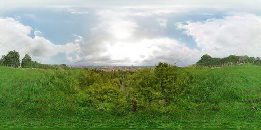


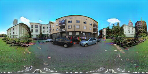


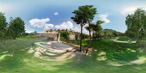


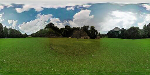


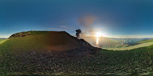


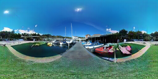


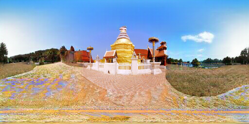

Figure 6.8: Extended results of optimizing the label "Lawn"
Input
Image Conditioned
to Street
Ground Truth


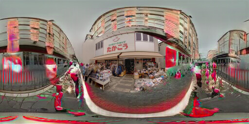


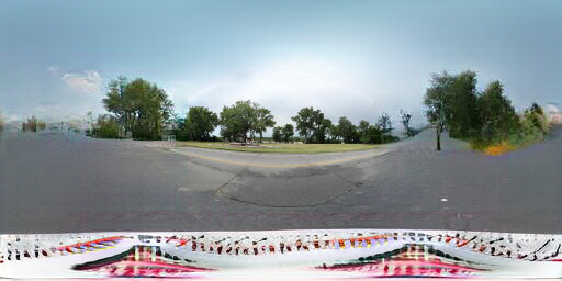


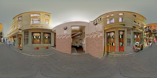


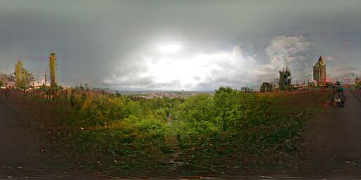


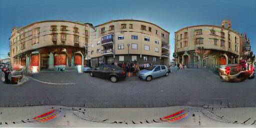


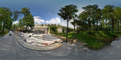


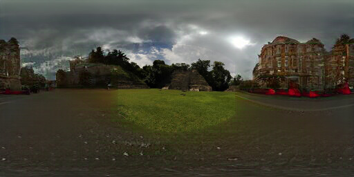


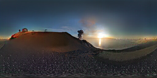


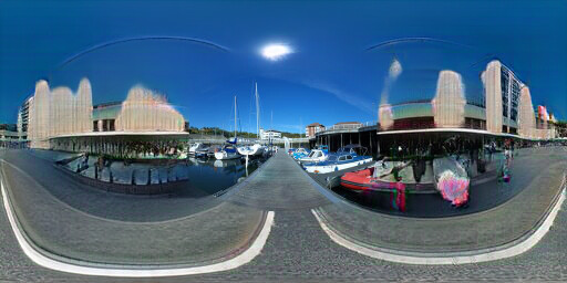


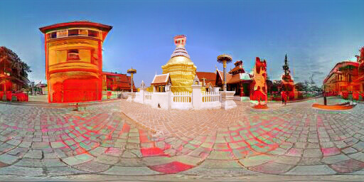

Figure 6.9: Extended results of optimizing the label "Street"
Input
Image Conditioned
to Lagoon
Ground Truth


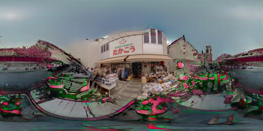


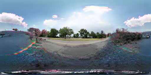


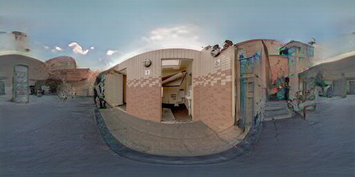


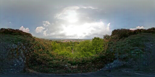


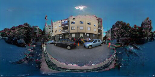


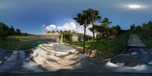


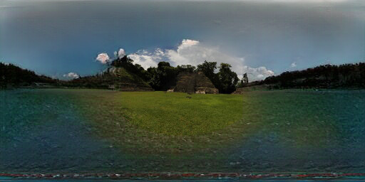


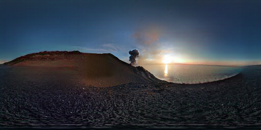


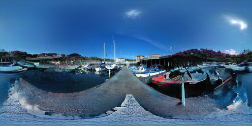


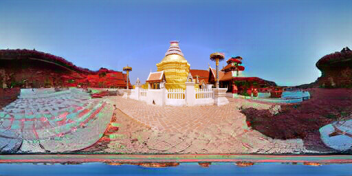

Figure 6.10: Extended results of optimizing the label "Lagoon"
We follow the same process for ten indoor scenes and ten top-1 indoor labels.
Input
Image conditioned
to Artistic Loft
Ground truth
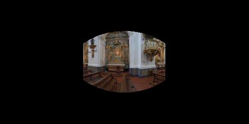
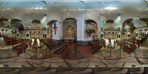
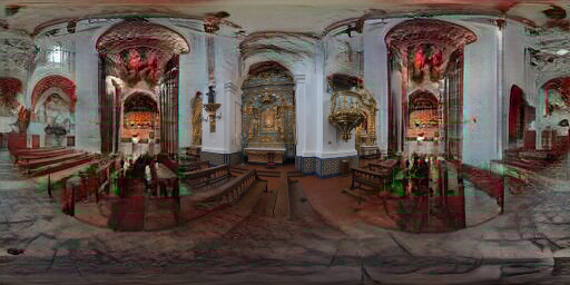
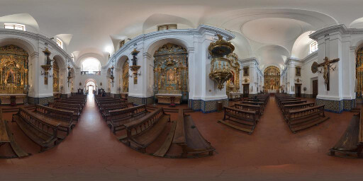
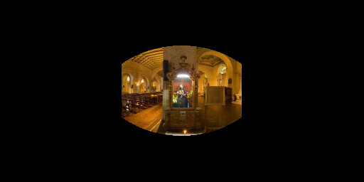
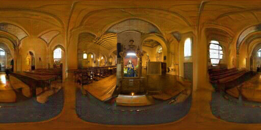
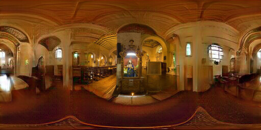
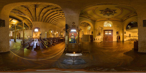
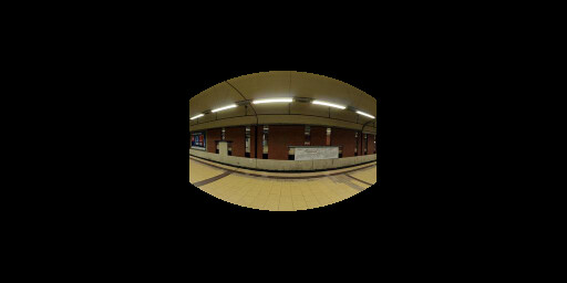
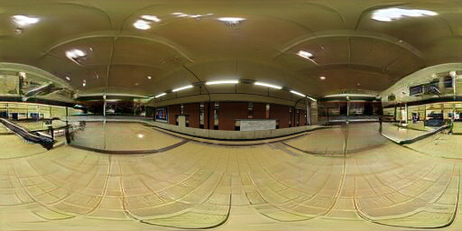
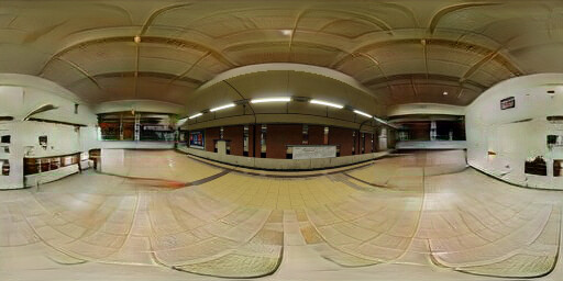
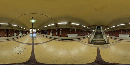
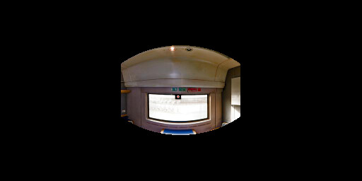
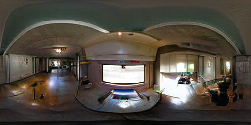
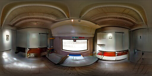
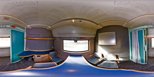
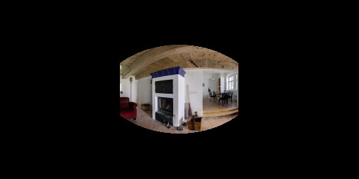
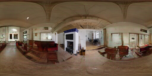
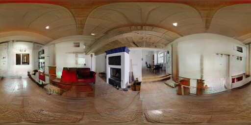
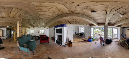
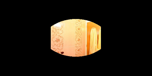
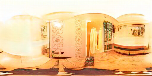
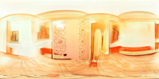
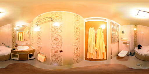
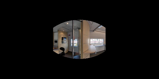
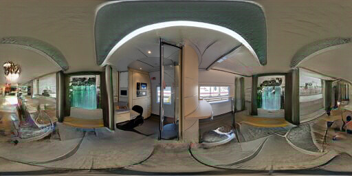
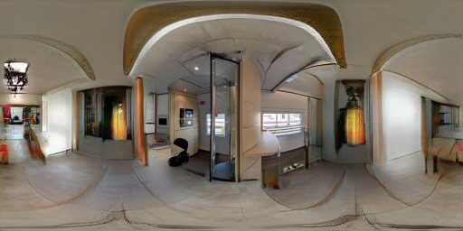
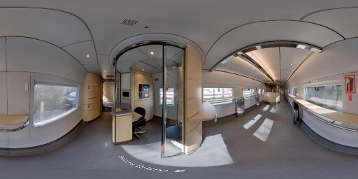
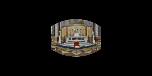
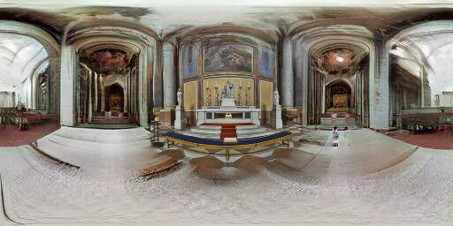
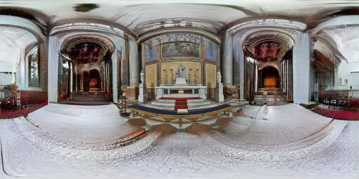
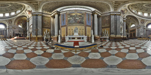
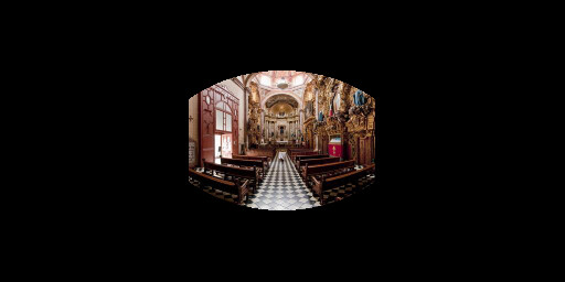
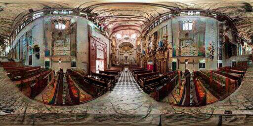
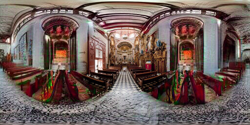
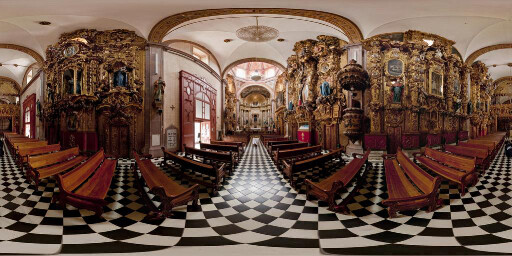
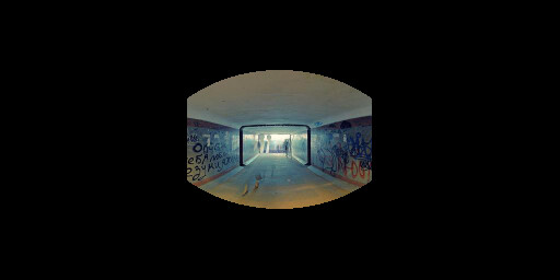
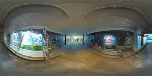
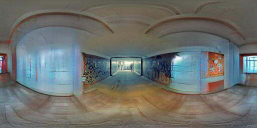
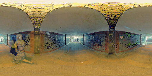
Figure 6.11: Extended results of optimizing the label "Artists loft"
Input
Image conditioned
to Throne Room
Ground truth


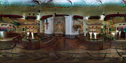


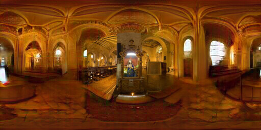


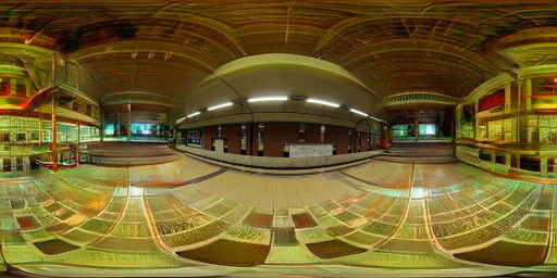


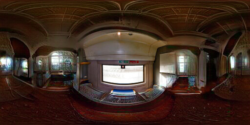


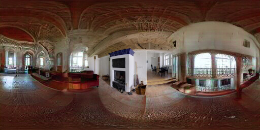


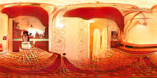


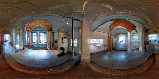


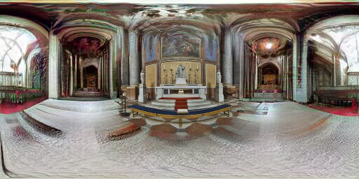


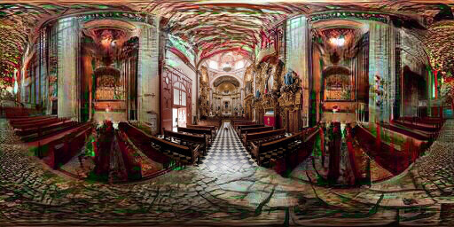


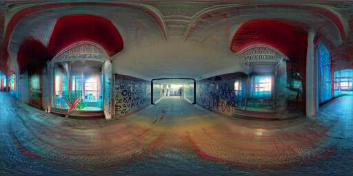

Figure 6.12: Extended results of optimizing the label "Throne Room"
Input
Image conditioned
to Corridor
Ground truth


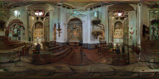


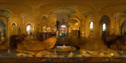


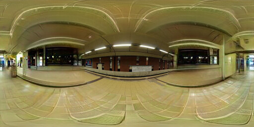


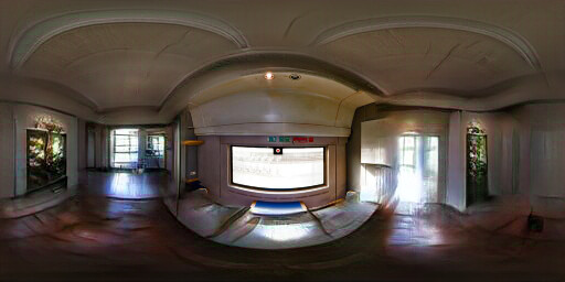


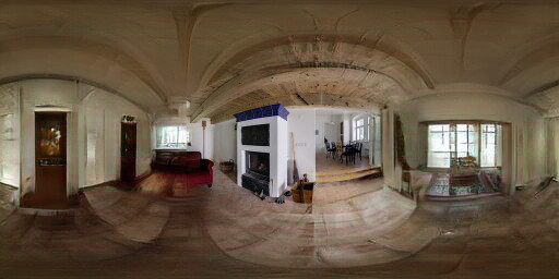


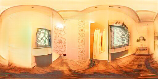


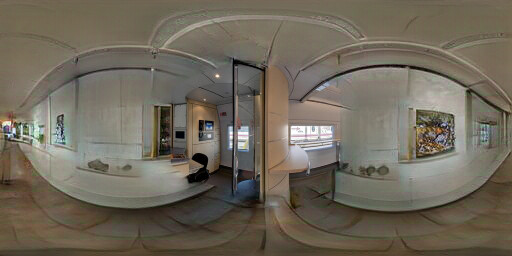


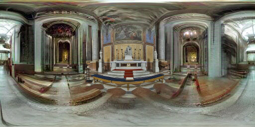


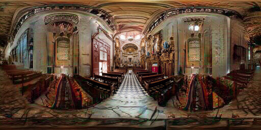


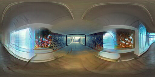

Figure 6.13: Extended results of optimizing the label "Corridor"
Input
Image conditioned
to Entrance Hall
Ground truth


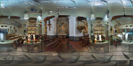


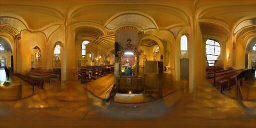


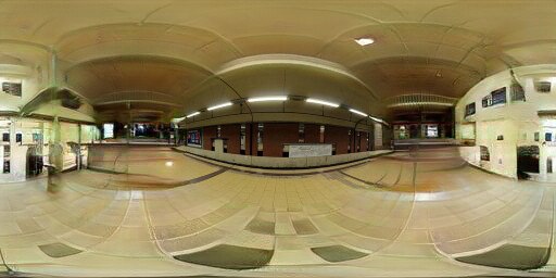


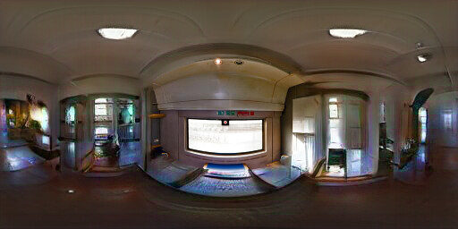


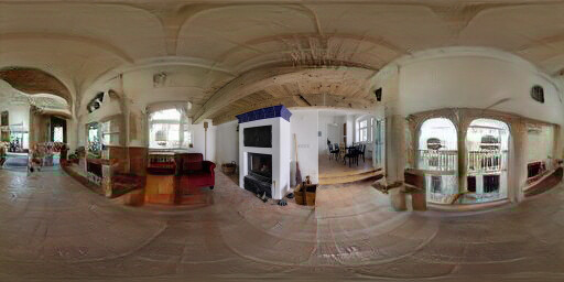


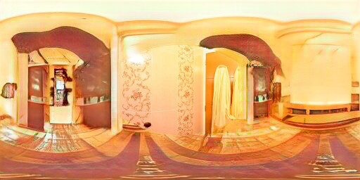


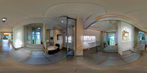


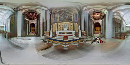


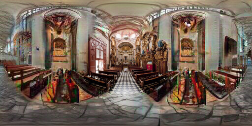


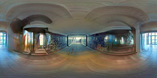

Figure 6.14: Extended results of optimizing the label "Entrance Hall"
Input
Image conditioned
to Amusement Arcade
Ground truth


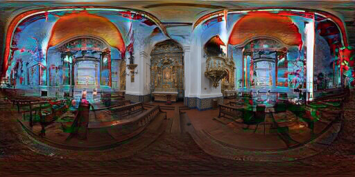


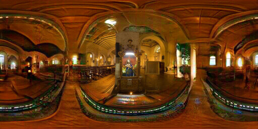


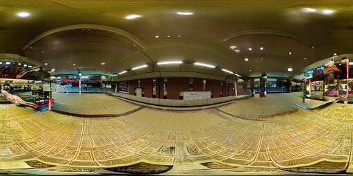


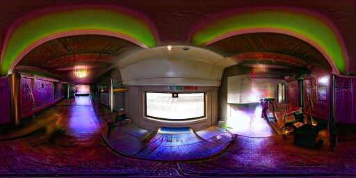


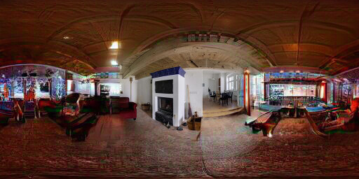


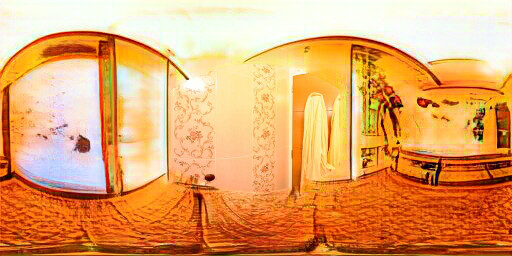


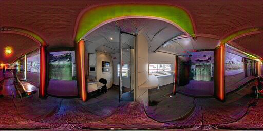


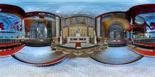


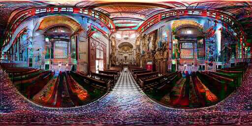


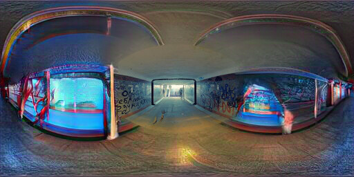

Figure 6.15: Extended results of optimizing the label "Amusement Arcade"
Input
Image conditioned
to Church
Ground truth


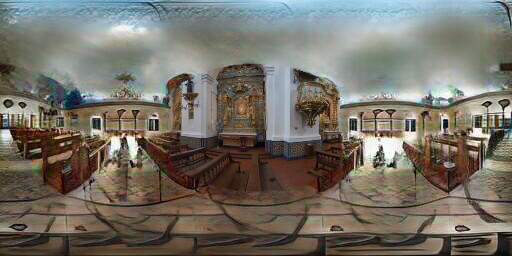


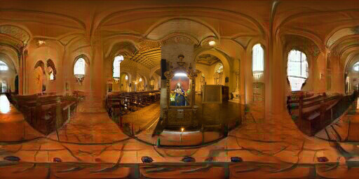


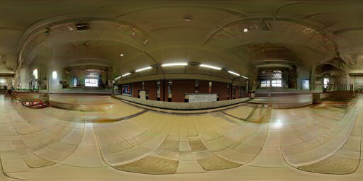


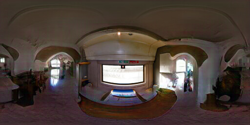


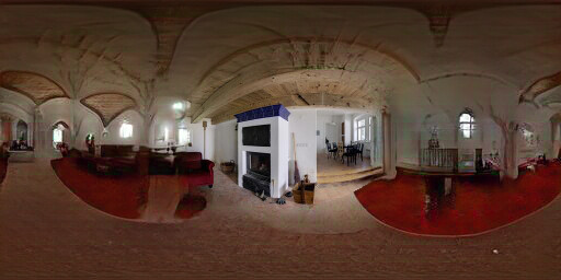


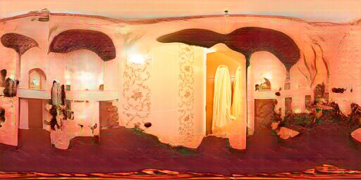


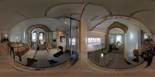


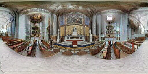


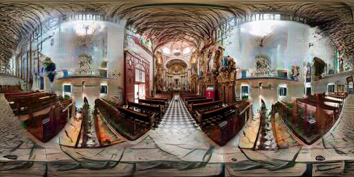


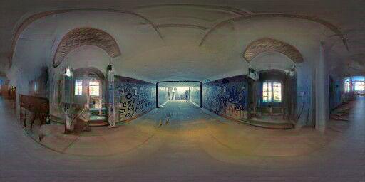

Figure 6.16: Extended results of optimizing the label "Church (indoor)"
Input
Image conditioned
to Art Galley
Ground truth


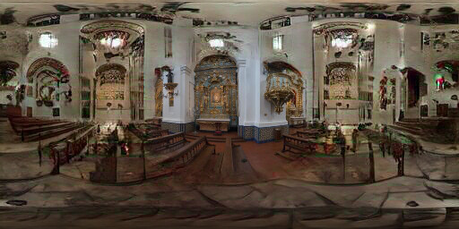


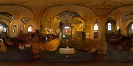


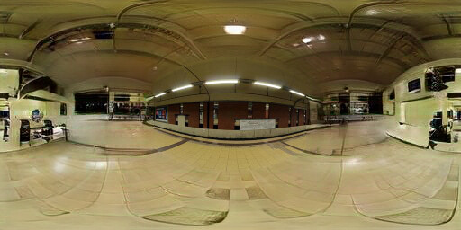


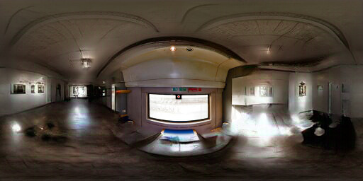


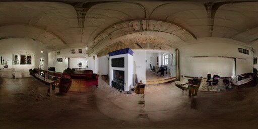


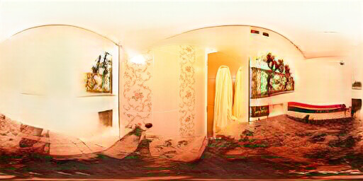


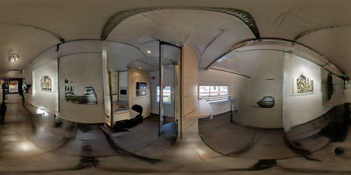


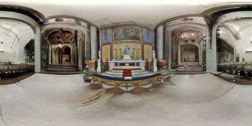


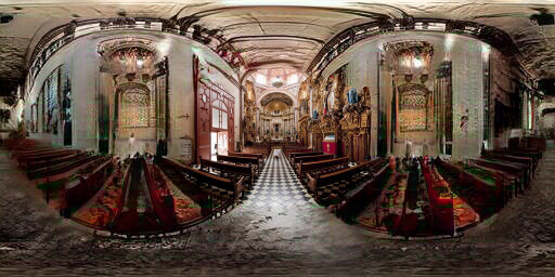


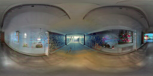

Figure 6.17: Extended results of optimizing the label "Art Gallery"
Input
Image conditioned
to Reception
Ground truth


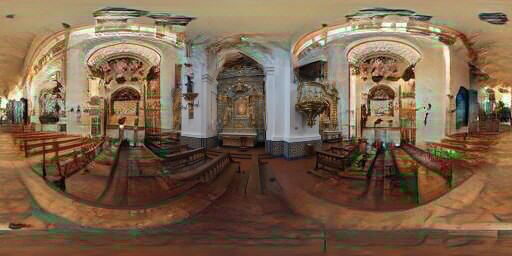


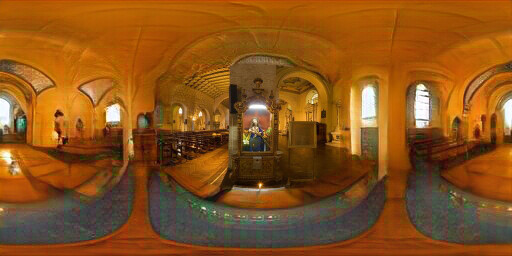


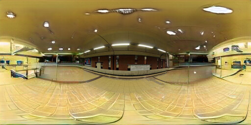


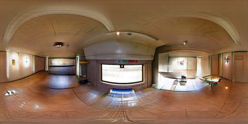


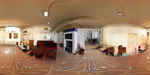


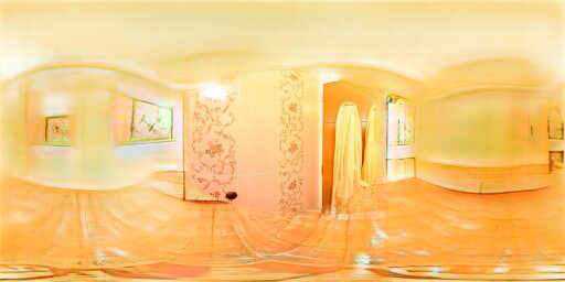


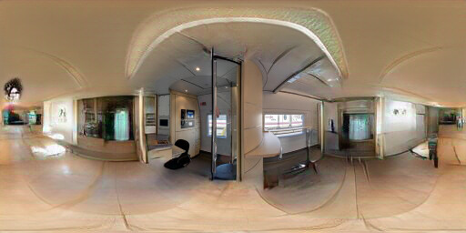


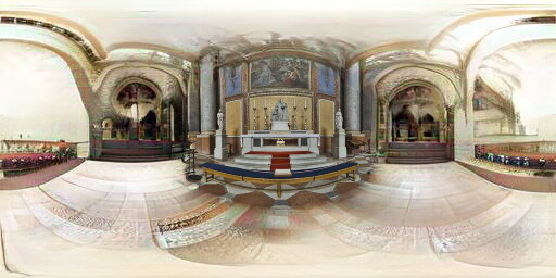


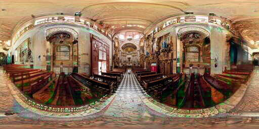


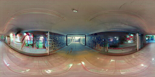

Figure 6.18: Extended results of optimizing the label "Reception"
Input
Image conditioned
to Bar
Ground truth


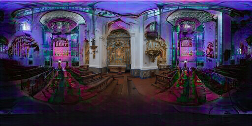


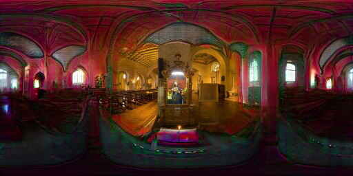


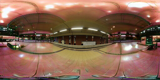


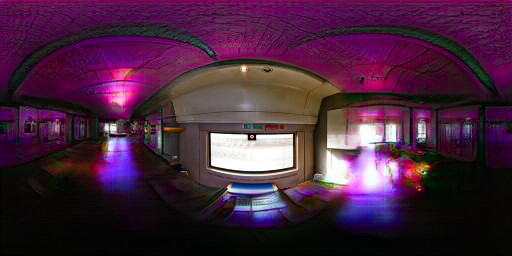


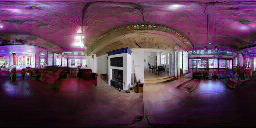


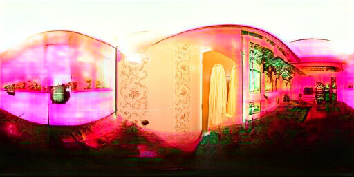


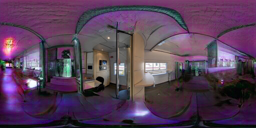


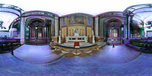


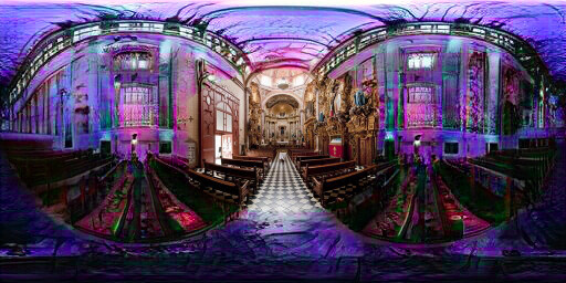


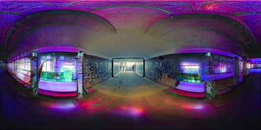

Figure 6.19: Extended results of optimizing the label "Bar"
Input
Image conditioned
to Bar
Ground truth


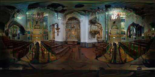


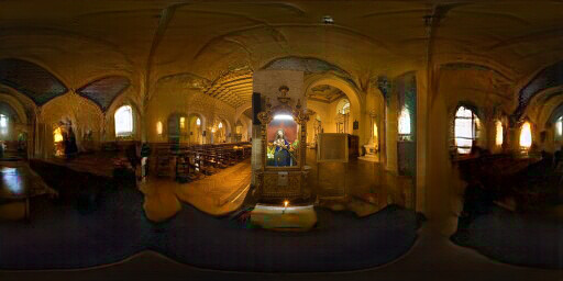


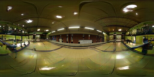


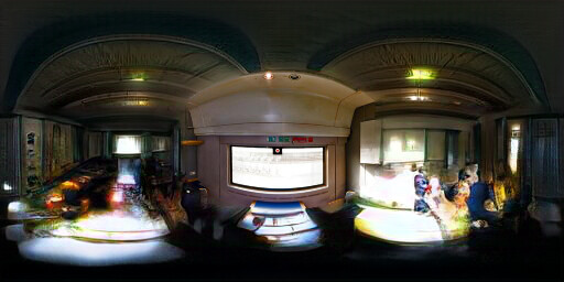


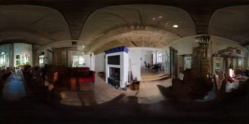


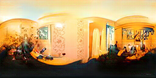


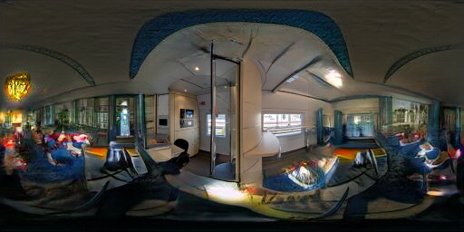


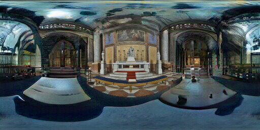


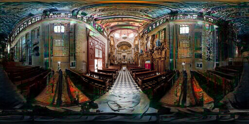


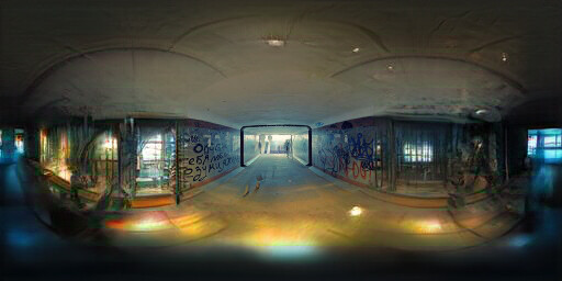

Figure 6.20: Extended results of optimizing the label "Pub (indoor)"
7. Linear interpolation in g space
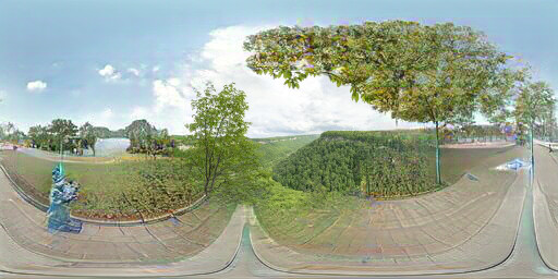
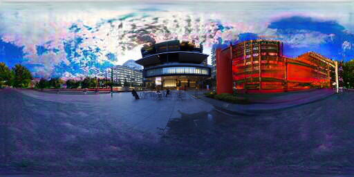
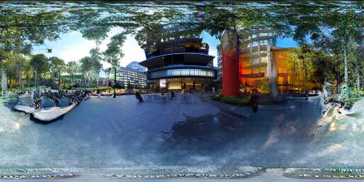
Here, we generate a smooth progression from one target label to another by linearly interpolating between the optimized g* vectors, and having the synthesis network generate the intermediate panoramas to obtain an animation. Observe how, for example trees give way to a paved walk in the “image conditioned -> promenade”, buildings turn to trees in the “sky -> picnic area”, and buildings progressively disappear in the “street -> beach” animations. In all these cases, the original image is realistically maintained in the center of the field of view.
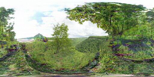
Image conditioned
Linear interpolation
-> Promenade
-> Sky
Linear interpolation
-> Picnic area
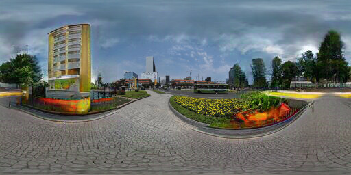
-> Street
Linear interpolation
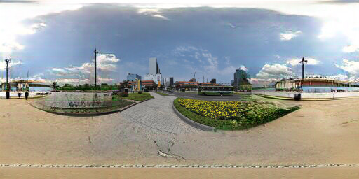
-> Beach
Figure 7.1: Linear interpolation in g* space.
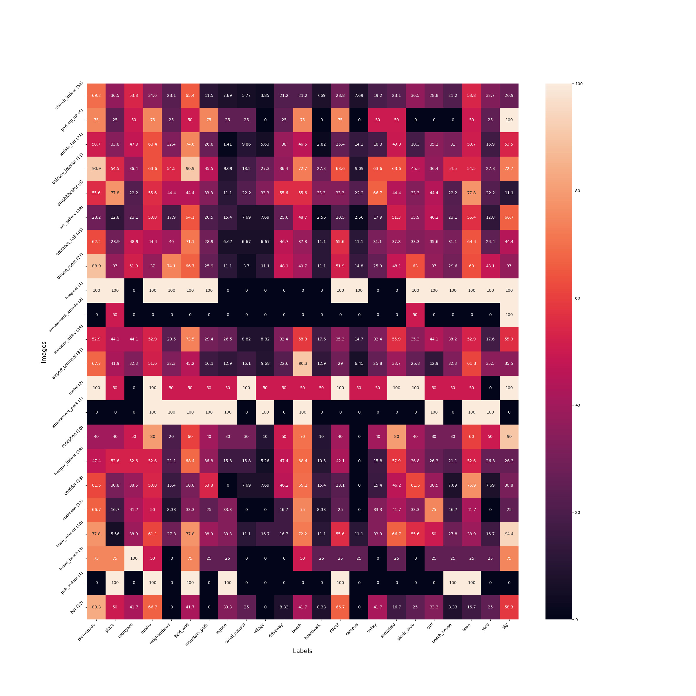
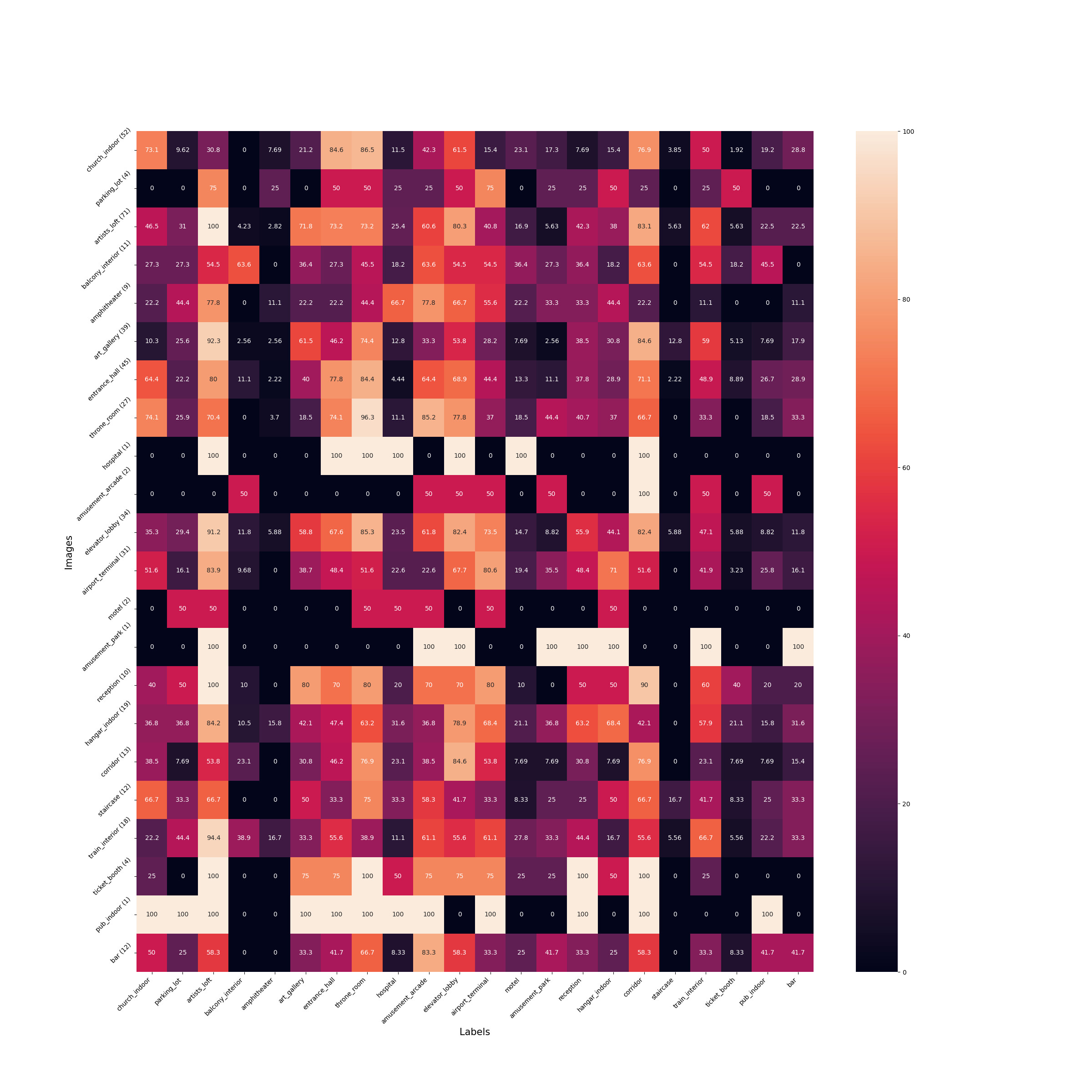
8. Percentage of success of the guidance process
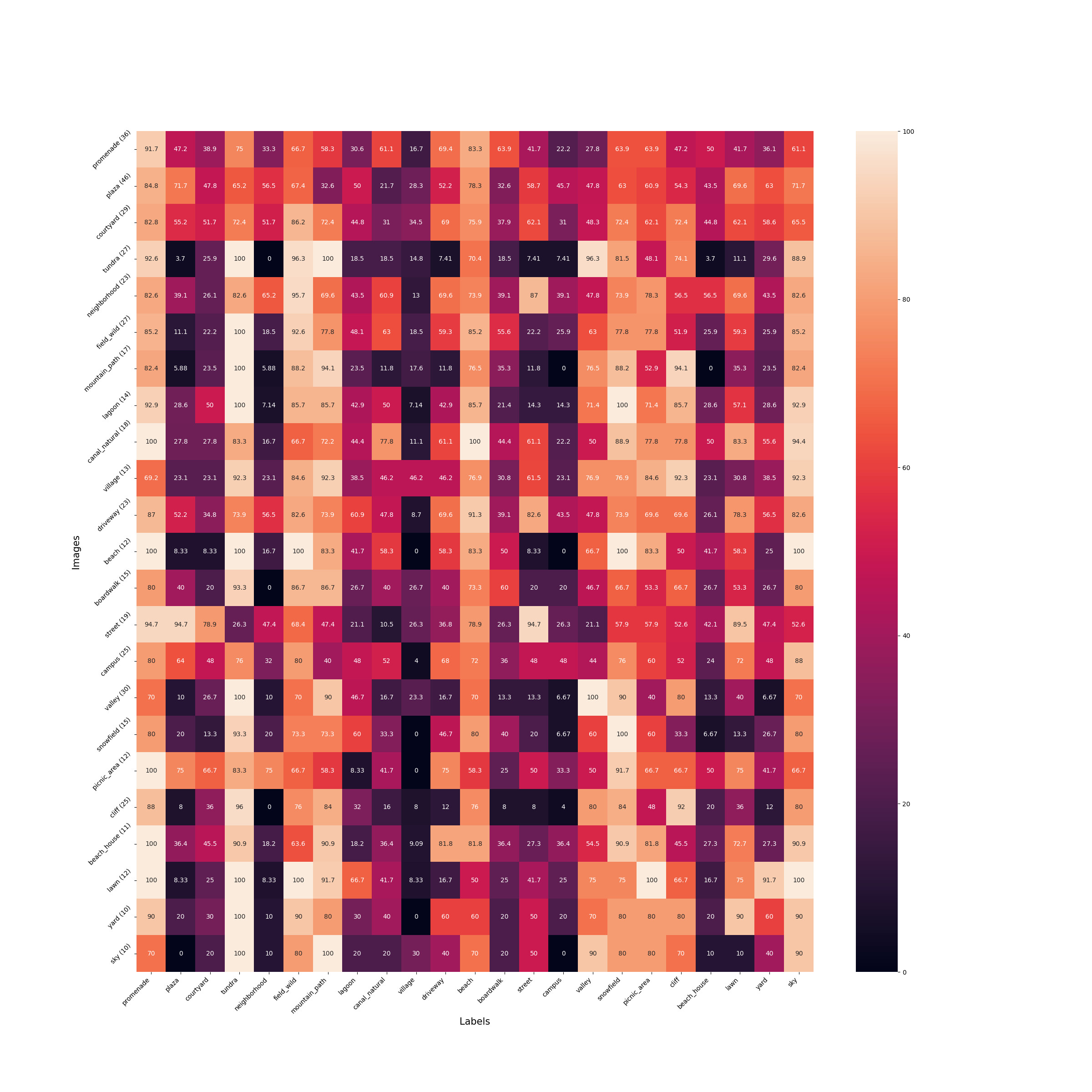
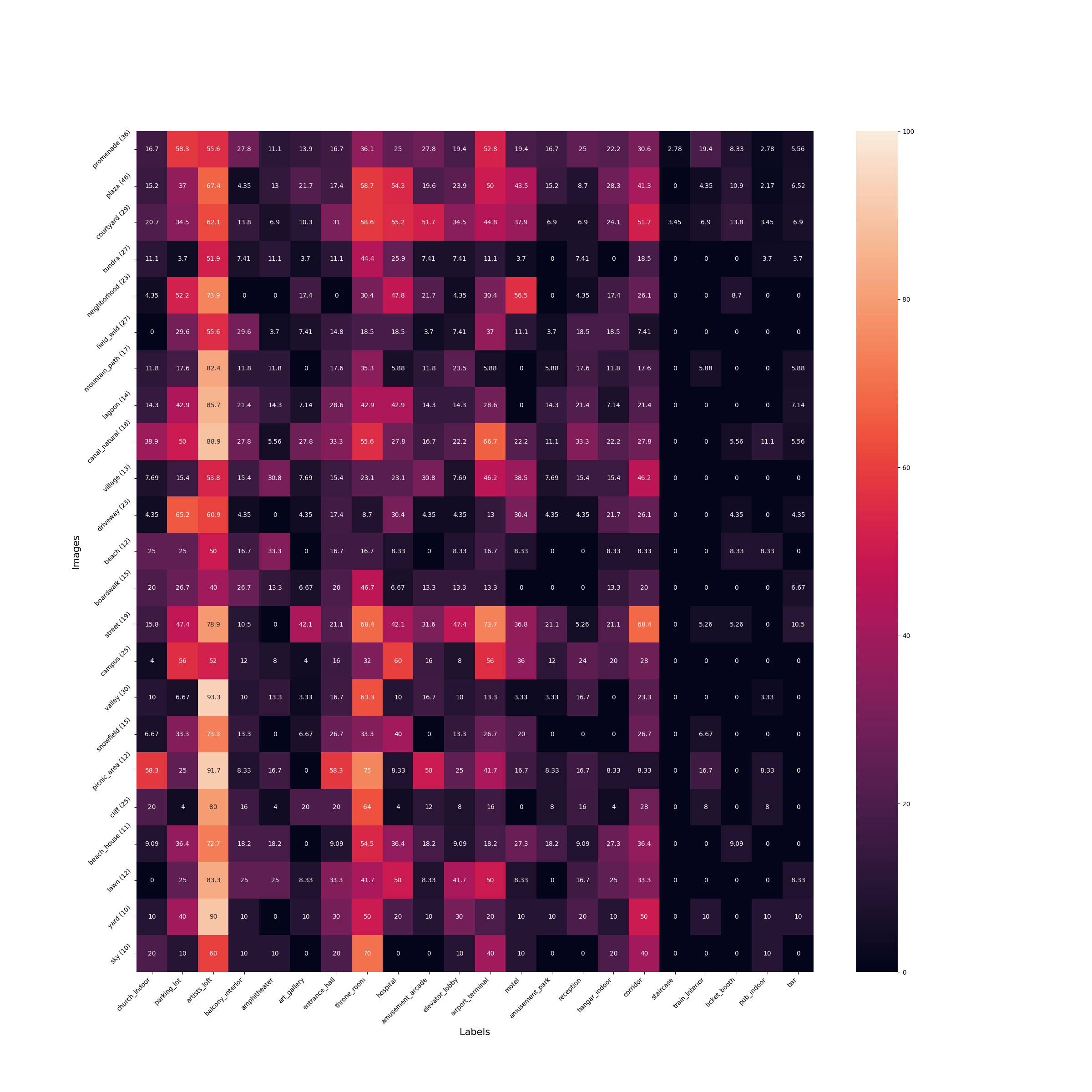
We provide a more detailed analysis similar to fig. 6 of the main paper. Instead of dividing input images into two categories of indoor and outdoor, we find the top-5 labels representing each input image. Then, we follow the same process as explained in section 6.2 of the main paper. The number of images representing each label is shown in parenthesis next to the label. Please click on each image to expand.
9. Editing with our method vs. InterfaceGAN
To compare the performance of our editing technique vs. InterfaceGAN, we follow the same strategy as the previous section and provide the output of the same target labels for the same scenes.
Input
Ours
InterfaceGAN


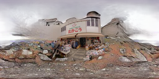


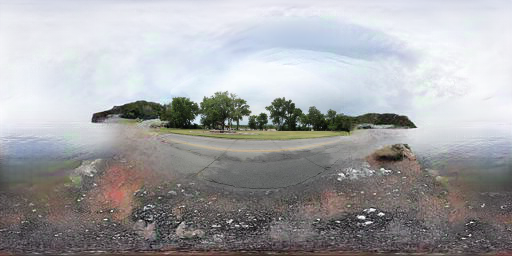


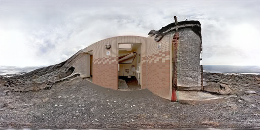


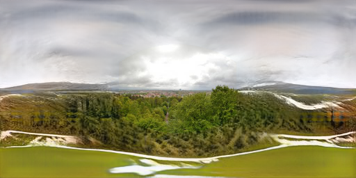


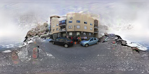


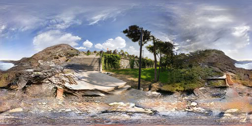


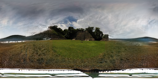


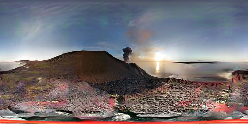


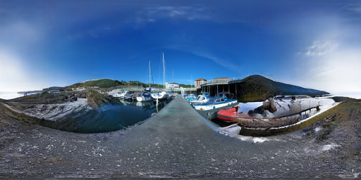


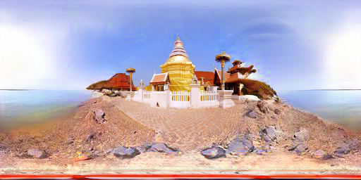
Figure 9.1: Extended comparison between our method of editing and InterfaceGAN for the label "Tundra".
Input
Ours
InterfaceGAN


Figure 9.2: Extended comparison between our method of editing and InterfaceGAN for the label "Sky".
Input
Ours
InterfaceGAN


Figure 9.3: Extended comparison between our method of editing and InterfaceGAN for the label "Snow Field".
Input
Ours
InterfaceGAN


Figure 9.4: Extended comparison between our method of editing and InterfaceGAN for the label "Beach".
Input
Ours
InterfaceGAN


Figure 9.5: Extended comparison between our method of editing and InterfaceGAN for the label "Mountain Path".
Input
Ours
InterfaceGAN


Figure 9.6: Extended comparison between our method of editing and InterfaceGAN for the label "Cliff".
Input
Ours
InterfaceGAN


Figure 9.7: Extended comparison between our method of editing and InterfaceGAN for the label "Picnic area".
Input
Ours
InterfaceGAN


Figure 9.8: Extended comparison between our method of editing and InterfaceGAN for the label "Lawn".
Input
Ours
InterfaceGAN


Figure 9.9: Extended comparison between our method of editing and InterfaceGAN for the label "Street".
Input
Ours
InterfaceGAN


Figure 9.10: Extended comparison between our method of editing and InterfaceGAN for the label "Lagoon".
Input
Ours
InterfaceGAN


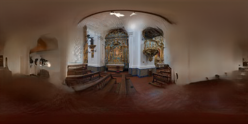


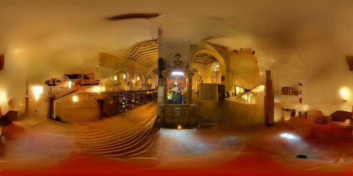


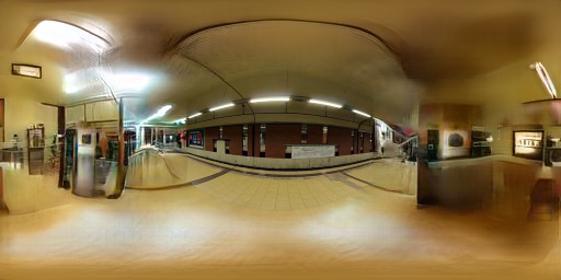


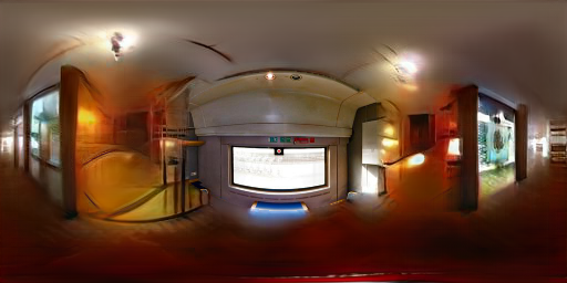


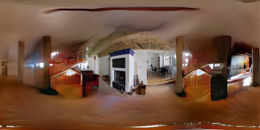


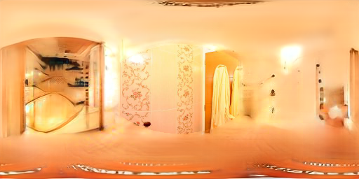


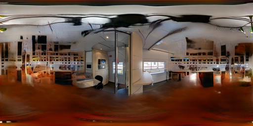


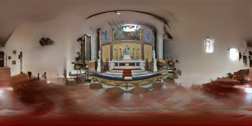


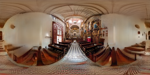


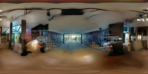
Figure 9.11: Extended comparison between our method of editing and InterfaceGAN for the label "Artists loft".
Input
Ours
InterfaceGAN


Figure 9.12: Extended comparison between our method of editing and InterfaceGAN for the label "Throne Room".
Input
Ours
InterfaceGAN


Figure 9.13: Extended comparison between our method of editing and InterfaceGAN for the label "Corridor".
Input
Ours
InterfaceGAN


Figure 9.14: Extended comparison between our method of editing and InterfaceGAN for the label "Entrance Hall".
Input
Ours
InterfaceGAN


Figure 9.15: Extended comparison between our method of editing and InterfaceGAN for the label "Amusement Arcade".
Input
Ours
InterfaceGAN


Figure 9.16: Extended comparison between our method of editing and InterfaceGAN for the label "Church (indoor)".
Input
Ours
InterfaceGAN


Figure 9.17: Extended comparison between our method of editing and InterfaceGAN for the label "Art Gallery".
Input
Ours
InterfaceGAN


Figure 9.18: Extended comparison between our method of editing and InterfaceGAN for the label "Reception".
Input
Ours
InterfaceGAN


Figure 9.19: Extended comparison between our method of editing and InterfaceGAN for the label "Bar".
Input
Ours
InterfaceGAN


Figure 9.20: Extended comparison between our method of editing and InterfaceGAN for the label "Pub (indoor)".
10. Virtual object compositing
One of our goals when extrapolating the field of view of an image beyond the camera frame boundary is to produce plausible surroundings.
This context is especially useful when inserting highly reflective objects with low roughness, as unseen parts of the environment are reflected onto the virtual object.
Here, we go a step further and take advantage of the recent developments in monocular depth estimation to produce an entire 3D environment around the camera.
We first project a part of the panorama output by our method onto an image plane, effectively simulating a camera.
We perform this at every 90˚ interval in azimuth and [-45, 0, 45]˚ in elevation within the panorama output by our method,
which yields 12 regular limited field of view images. We use a field of view of 100˚ with an aspect ratio of 1:1 to perform the projection.
We then estimate the depth of each image individually.
To estimate depth from the images, we leverage a SegFormer [3] architecture trained using eq. (7) from [4] on the following datasets: [5, 6, 7, 8, 9, 10, 11, 12, 13, 14].
It would be possible to directly train on panoramas, however the data is not as abundant and results in lower accuracy and robustness.
We execute our depth estimation method on each of the 12 images extracted from the hallucinated panorama and merge the result in spherical space.
To do so, we convert the estimated depth from the image plane to the distance from the panorama's center.
Then, we estimate a scaling factor in distance-space between each neighboring depth estimation using least-squares on the overlapping regions.
Once this best-fit scaling is applied across all images, we merge the overlapping distances by averaging them, weighted by their Euclidean Distance Transform from the image border.
After this step, we are left with a spherical point cloud aligned on a regular grid, which we use to build a mesh.
Groups of three neighboring point cloud are set as a triangle vertex. The result is an editable 3D environment with the camera at the origin.
We use Blender Cycles to render virtual objects within the extrapolated 3D mesh and perform the compositing with the original input image.
The panoramas predicted by our method are detailed enough to enable the generation of realistic reflections off of the surface of shiny objects.
The additional post-processing (explained above) creates spatially-varying reflections that vary as a function of the position of the virtual object in the scene,
thereby further increasing the realism.
Because of its guided editing capabilities, our approach enables a user to modify the appearance of the extrapolated field of view, and thus control the appearance of the objects.
Please play each video to see the effect.
(A)
(B)
(C)
Figure 10.1: Examples of inserting virtual objects in a scene using the output of our method for image-based lighting. Following the post-processing step described in section 8 of this document, we can acheive realistic rendering of virtual glossy objects with spatially-varying reflections (A). In addition, our method enables modifying the appearance of synthetic glossy objects by editing the content of environment maps. For example, we can add more trees to the scene as a picnic area (B) or add tile textures to the ground as a promenade (C).
We can also smoothly blend between target labels while rendering a virtual object in the photograph, resulting in realistic and diverse reflections of the object while staying faithful to the background image.
Figure 10.2: Rendering a shiny synthetic object in a scene while smoothly blending between different target labels
11. Guided face editing
To demonstrate the effectiveness of our method on other domains, we also trained our model on the face domain. We start from the FFHQ dataset and use Microsoft Face API to extract attributes of faces such as Age, Happiness, Sunglasses, etc. In addition, we segment the face area (face skin, mouth, ears, eyes, nose) in each image. As a result, we have a dataset $D = \{\bo{x}_{i}, g_{i}, m_{i}\}_{i=1}^{N}$, in which $N$ is the total number of images, and $\bo{x}_{i}$, $g_{i}$, $m_{i}$ are the image, guide and a binary mask of face of the $i$-th image in the dataset. We then train our proposed model on this dataset by replacing warping with masking. Our method enables us to guide the inpainting based on the attributes as shown in the following figure.

Figure 11.1: Face editing using our method
12. Nearest neighbors
To show that our network does not memorize the images in the dataset, we provide three examples of the nearest neighbours in the train set for the generated images in the figure below.

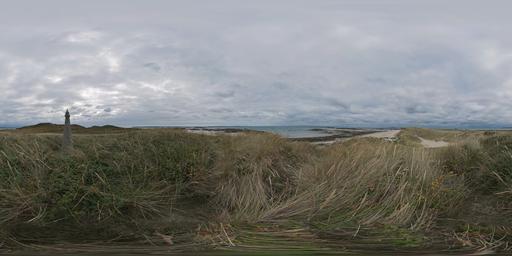
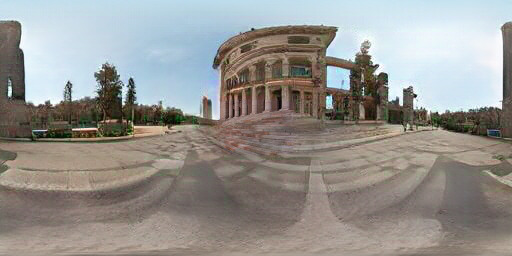
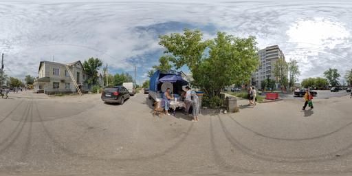
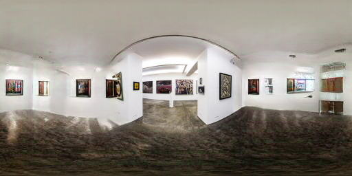
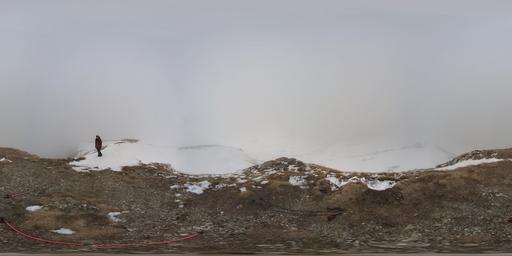
Figure 12.1: Nearest neighbour in the train set for the generated images
13. Movie scenes
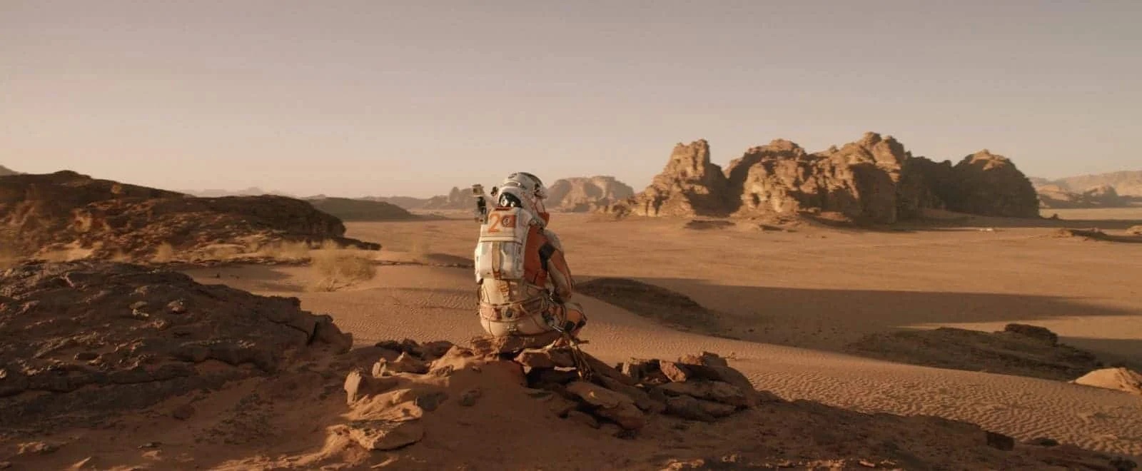
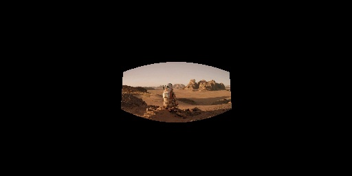
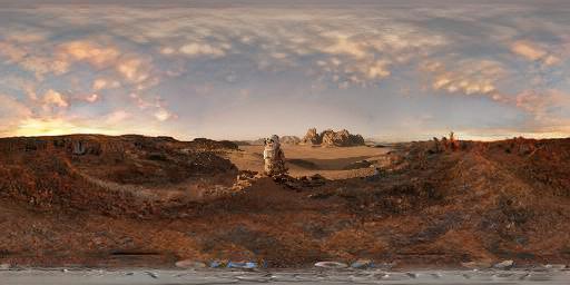
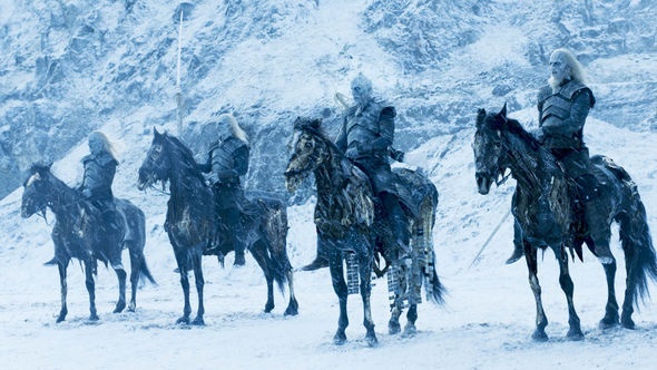
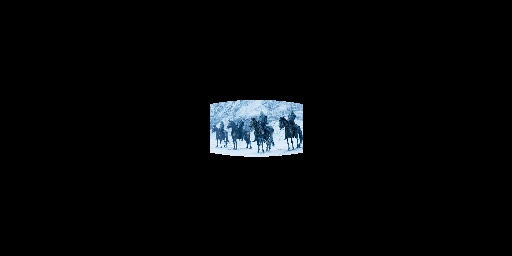
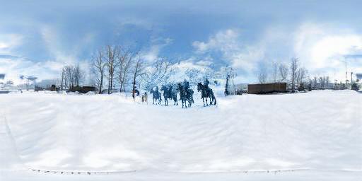
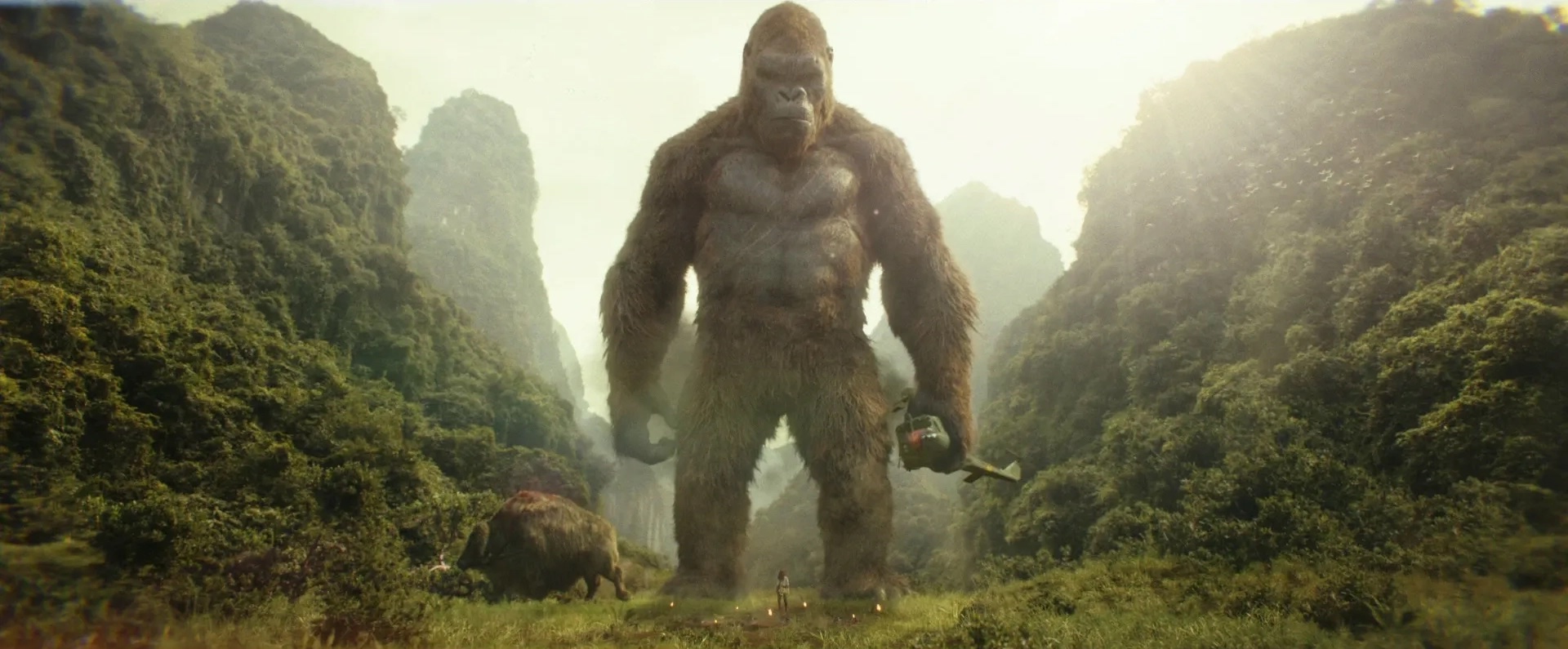
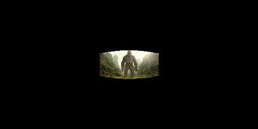
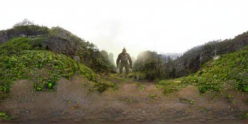
To evaluate the robustness of our method, we tested it on some highly VFX-based movie scenes. These scenes contain information that does not exist in the real world (hopefully!). We use the Hold-Geoffroy et al. [18] technique to estimate the camera parameters and use them to project the scenes into the panoramic representation. Then, we use our method to extrapolate the 360° FOV. The following figures show the output of our approach. Although these scenes contain out-of-domain information, our method still predicts reasonable context.
Scene 1: The Martian, courtesy of 20th Century Fox.
Scene 2: Game of Thrones, courtesy of HBO.
Scene 3: Kong: Skull Island, courtesy of Warner Bros. Pictures.
References
[1] Ting-Chun Wang, Ming-Yu Liu, Jun-Yan Zhu, Andrew Tao, Jan Kautz, and Bryan Catanzaro. High-resolution image synthesis and semantic manipulation with conditional gans.
In CVPR 2018.
[2] Takayuki Hara, Yusuke Mukuta, and Tatsuya Harada. Spherical image generation from a single image by considering scene symmetry. In AAAI 2021.
[3] Xie E, Wang W, Yu Z, Anandkumar A, Alvarez JM, Luo P. SegFormer: Simple and Efficient Design for Semantic Segmentation with Transformers. arXiv preprint arXiv:2105.15203.
[4] Ummenhofer B, Zhou H, Uhrig J, Mayer N, Ilg E, Dosovitskiy A, Brox T. Demon: Depth and motion network for learning monocular stereo. In CVPR 2017.
[5] Vasiljevic I, Kolkin N, Zhang S, Luo R, Wang H, Dai FZ, Daniele AF, Mostajabi M, Basart S, Walter MR, Shakhnarovich G. Diode: A dense indoor and outdoor depth dataset. arXiv preprint arXiv:1908.00463..
[6] Gehrig M, Aarents W, Gehrig D, Scaramuzza D. Dsec: A stereo event camera dataset for driving scenarios. IEEE Robotics and Automation Letters 2021.
[7] Madai-Tahy L, Otte S, Hanten R, Zell A. Revisiting deep convolutional neural networks for RGB-D based object recognition. In ICANN 2016.
[8] Vankadari MB, Kumar S, Majumder A, Das K. Unsupervised Learning of Monocular Depth and Ego-Motion using Conditional PatchGANs. In IJCAI 2019.
[9] Wang W, Zhu D, Wang X, Hu Y, Qiu Y, Wang C, Hu Y, Kapoor A, Scherer S. Tartanair: A dataset to push the limits of visual slam. In IROS 2020.
[10] Silberman N, Hoiem D, Kohli P, Fergus R. Indoor segmentation and support inference from rgbd images. In ECCV 2012.
[11] Li Z, Snavely N. Megadepth: Learning single-view depth prediction from internet photos. In CVPR 2018.
[12] Wang Q, Zheng S, Yan Q, Deng F, Zhao K, Chu X. Irs: A large synthetic indoor robotics stereo dataset for disparity and surface normal estimation. arXiv e-prints. 2019 Dec:arXiv-1912.
[13] Roberts M, Ramapuram J, Ranjan A, Kumar A, Bautista MA, Paczan N, Webb R, Susskind JM. Hypersim: A photorealistic synthetic dataset for holistic indoor scene understanding. In ICCV 2021.
[14] Garg R, Wadhwa N, Ansari S, Barron JT. Learning single camera depth estimation using dual-pixels. In ICCV 2019.
[15] Karras, T., Laine, S., Aittala, M., Hellsten, J., Lehtinen, J., Aila, T. Analyzing and improving the image quality of stylegan. In CVPR 2020.
[16] Zhao, S., Cui, J., Sheng, Y., Dong, Y., Liang, X., Chang, E.I., Xu, Y. Large Scale Image Completion via Co-Modulated Generative Adversarial Networks. In ICLR 2021.
[17] R. I. Hartley and A. Zisserman. Multiple View Geometry in Computer Vision. Cambridge University Press, second edition, 2004.
[18] Yannick Hold-Geoffroy, Kalyan Sunkavalli, Jonathan Eisenmann, Matt Fisher, Emiliano Gambaretto, Sunil Hadap, and Jean-François Lalonde. A perceptual measure for deep single image camera calibration. In CVPR 2018.
